
Most valve problems do not begin with a dramatic failure. You first notice a damp stem, a warmer line, a slower cylinder, or a handle that needs more force than it did last month. Good hydraulic valve maintenance catches those changes early, keeps contamination out, preserves approved settings, and confirms performance after any work.
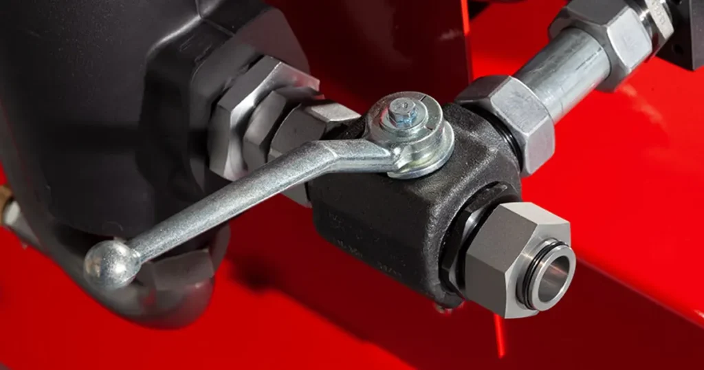
Your maintenance interval should follow the way the machine works, not a generic calendar. A valve on a clean indoor test bench does not face the same contamination, vibration, temperature swings, or duty cycle as one on a dusty mobile machine. Shorten the interval when the service is severe or a failure could create a safety risk.
What maintenance is trying to prevent
| Degradation | What you may notice | Maintenance response |
|---|---|---|
| Solid-particle contamination | Sticking, check leakage, blocked orifice or erratic flow | Control ingress, sample fluid, service filtration and clean by approved methods |
| Water or degraded fluid | Corrosion, poor lubrication, seal damage, varnish or instability | Investigate the source, test fluid and follow the system fluid-change procedure |
| Seal aging or incompatibility | Seepage, rising torque or internal leakage | Confirm fluid, temperature and seal material before replacement |
| Seat or control-edge damage | Reverse leakage, drift, poor shut-off or changed metering | Isolate the path; repair only under an approved procedure |
| Loose mounting or pipe strain | Vibration, interface leak, distortion or hard operation | Correct support/alignment and restore specified torque |
| Adjustment movement | Changed speed, instability or heat | Compare with the documented baseline; do not guess |
| Corrosion or impact | Pitting, damaged handle, unreadable marking or body damage | Remove the cause and replace when integrity is uncertain |
| Excess pressure drop | Hot valve, slow actuator and wasted power | Measure Δp at known flow; check position, blockage and sizing |
Safety comes before the checklist
Before you inspect or adjust the valve, follow the machine manufacturer’s isolation procedure. Lock out every energy source, lower or mechanically support the load, relieve trapped pressure, and discharge accumulators. Then confirm the relevant circuit section is depressurized at a suitable test point with a rated instrument.
Do not use your hand to find a leak or loosen a fitting to prove pressure is gone. Some checks require a running circuit; perform them only under an approved procedure with guards, rated instruments, secure connections and trained personnel clear of the hazard zone.
Build a baseline before the valve develops a fault
After commissioning or a verified repair, record:
- Valve model, size, ports and flow direction
- Fluid, normal temperature and cleanliness target
- Normal system pressure and valve Δp at a known flow
- Permitted internal or reverse leakage
- Handle or actuator effort and cycle behavior
- Throttle, flow-control or relief setting and lock condition
- Typical actuator speed, load holding and cycle time
- Photographs of orientation, marking and external condition
Without a baseline, comments such as the handle feels tighter or the cylinder seems slower are hard to act on. With recorded pressure, flow, temperature, leakage, operating effort, and cycle time, you can see a trend before it turns into downtime.
A practical hydraulic valve maintenance schedule
Use the schedule below as a starting point, then adjust it from your machine manual, valve instructions, risk assessment, oil analysis, and service history. If a reading moves away from the baseline, inspect by condition rather than waiting for the next calendar date.
| Timing | Checks | Action trigger |
|---|---|---|
| Before operation or each shift in severe service | Visible leaks, damaged controls, loose guards, hose strain, unusual noise and reservoir level | Fresh leak, damaged pressure boundary, unsafe control or unexplained noise |
| Weekly or routine operator round | Position marks, mounting, corrosion, local heat and filter indicator | Moved adjustment, rising temperature, vibration, corrosion or warning |
| Planned maintenance interval | Fluid sample, filter differential, seals, functional cycling and baseline comparison | Cleanliness outside target, abnormal Δp, leakage, delay or repeatability change |
| Extended shutdown | Corrosion protection, caps, actuator position, moisture and storage condition | Contamination, corrosion, seized linkage or degraded seals |
| Event-based | Inspect after overpressure, overheating, contamination, hose/pump failure or crash | Any event that can send debris, overload or heat through the valve |
| After repair or replacement | Part/orientation, cleanliness, settings, leakage, function and Δp | Any result outside approved acceptance criteria |
Routine inspection: what to look for
External leakage
If you see oil around the valve, clean the safe, depressurized surface first and watch where fresh oil appears. Check the stem seal, plugs, body joints, flanges, threaded ports, and actuator interface. Do not assume tightening is the repair; the real cause may be the wrong seal material, overpressure, vibration, pipe strain, or a damaged sealing surface.
Mounting, line support and alignment
Valve bodies are not pipe supports. Check that hoses and tubes do not impose obvious bending or torsion. Confirm mounting hardware using the specified sequence and torque. If a handle or actuator becomes hard to move after piping work, investigate alignment and body distortion.
Temperature and pressure drop
A valve that is hotter than the surrounding line is giving you a useful clue, but surface temperature alone does not identify the cause. Reproduce the same operating condition and measure upstream pressure, downstream pressure, flow, and oil temperature. Then compare the pressure drop with the original baseline or approved product data.
Power loss (kW) ≈ Δp (bar) × Q (L/min) ÷ 600. For example, a 10-bar drop at 90 L/min turns about 1.5 kW into continuous heat. If you measure that across a valve that should be fully open, check its position, internal blockage, and sizing.
Operation and repeatability
Tip: If a manual valve starts sticking, do not reach for a longer handle. Compare pressure, alignment, contamination, and operating effort with the baseline before extra leverage damages the stem.
Fluid cleanliness is valve maintenance
Note: New oil is not automatically clean oil. A small particle introduced through an open hose or dirty transfer container can hold a check element off its seat, jam a spool, or block an orifice.
- Use clean, compatible transfer equipment rather than open buckets.
- Filter new fluid to the system requirement; new oil does not automatically mean clean oil.
- Keep caps on replacement valves and open lines until connection.
- Clean around a component before removal.
- Use lint-controlled materials near sealing surfaces.
- Investigate recurring contamination instead of repeatedly changing valves.
- Record sample location, temperature and operating condition.
ISO 4406:2021 provides a code for expressing particle contamination. It does not choose the correct target for your machine; that comes from the system and component requirements.
Maintenance by valve type
Hydraulic ball valves
- Confirm the valve reaches full open and full closed stops.
- Do not leave a standard shut-off ball valve partly open for regulation unless designed for it.
- Inspect the stem area, handle, stop plate and actuator coupling.
- Trend operating torque under comparable pressure conditions.
- Check leakage across the closed valve using an approved isolation method.
- If rarely operated, follow an approved exercise interval without disrupting a safety-critical process.
If you are maintaining a quarter-turn shut-off valve, use the ball valve maintenance guide and compare the installed unit with Chenyang’s hydraulic ball valve range.
Hydraulic check valves
- Verify direction and inspect for unexpected reverse leakage.
- Compare forward Δp at a known flow with the baseline.
- Listen for chatter, then confirm with pressure/flow measurement.
- Check cracking behavior with an instrument that can resolve it.
- Treat seat contamination as a system-cleanliness problem too.
If the check valve helps hold a load, treat any increase in drift as a safety-related symptom. Do not assume a general-purpose check valve provides a certified safety function. Before you condemn the check valve, isolate piston-seal leakage, hose expansion, thermal effects, and any parallel flow path.
Throttle and flow-control valves
- Record the adjustment before touching it and confirm the lock.
- Measure flow and Δp at a known temperature and load.
- For one-way valves, check restricted and free-flow directions separately.
- Inspect small passages only under an approved clean procedure.
- Do not expect a basic throttle to hold constant flow as load or viscosity changes.
If speed control is the issue, compare the symbol and flow direction with the hydraulic throttle valve and hydraulic flow-control valve pages. This helps you confirm whether you have a basic restriction, a one-way bypass, or a compensated control before you adjust it.
Preserve settings—do not tune away the evidence
When you move a relief, reducing, flow-control, or throttle adjustment, you also change pressure, force, speed, or heat somewhere in the circuit. Record the original position, locking method, and measured behavior before touching it. Only trained personnel should adjust it under the machine manufacturer’s procedure and within every component rating.
Tip: Change one controlled variable at a time. If you adjust several valves together, you lose the baseline and may create interacting faults that are harder to diagnose.
When disassembly is justified
Do not open the nearest valve simply because the machine symptom appears nearby. First use the hydraulic valve troubleshooting guide to separate pump, actuator, command, line, and valve causes. If the measurements point back to the valve, obtain the approved procedure, correct parts, and acceptance tests before disassembly.
- Depressurize, isolate and clean the work area.
- Mark ports, orientation and settings; take photographs.
- Cap exposed lines immediately with clean, compatible caps.
- Disassemble only as far as instructions permit.
- Keep matched and orientation-sensitive parts organized.
- Inspect seats, balls, poppets, spools, bores, springs, stems, seals and threads.
- Use the correct seal material and backup arrangement.
- Lubricate and tighten according to the approved fluid, sequence and torque.
Do not polish a spool, enlarge an orifice, lap a seat or machine a pressure-containing part in the field unless the manufacturer explicitly provides that method. Small geometry changes alter leakage, cracking pressure and control.
Post-maintenance testing
Easy hand movement after reassembly does not prove the valve will seal or control flow under pressure. Choose the required hydraulic valve testing from the parts you disturbed and the function the valve must perform.
| Maintenance action | Verification to consider |
|---|---|
| External seal or plug work | Pressure-boundary and external-leakage check |
| Seat, ball, poppet or closure work | Internal/reverse leakage, function and pressure integrity |
| Spring or check-element work | Cracking/reseating, forward Δp and reverse leakage |
| Throttle or metering-part work | Flow-versus-setting and both directions for one-way valves |
| Complete replacement | Part/orientation, flushing, leakage, function and baseline comparison |
Restart at controlled pressure and load. Watch for fresh leakage, unexpected actuator motion, pressure spikes, noise, and rising temperature before you return the machine to normal duty. Restore every guard and document the final settings and measured results.
Maintenance records worth keeping
- Valve model, serial/batch reference and circuit location
- Date, machine hours/cycles and reason for work
- Fluid sample and filter information
- Before/after pressure, flow, temperature, leakage and effort
- Original and final adjustments
- Parts and seal materials installed
- Failure photographs and suspected contamination source
- Test method, acceptance limits and result
- Technician and reviewer
Your maintenance records become most useful when failures repeat. If the same check valve leaks after every pump replacement, the debris released during the pump failure matters more than the calendar interval. That pattern tells you to improve flushing and contamination control, not simply replace another valve.
FAQ
How often should hydraulic valves be maintained?
There is no universal interval. Use the machine manual, valve manufacturer, duty, environment, fluid analysis, failure consequence and condition trends. Add event-based checks after overheating, contamination and overpressure.
Should hydraulic valves be lubricated?
Internal parts normally operate in system fluid. External linkages may have separate requirements. Do not add grease or oil unless the procedure specifies the product and location.
Can you clean a sticking hydraulic valve?
Sometimes, after you isolate the fault and control cleanliness. If a precision surface, seat or bore is damaged, cleaning will not restore it. Retest leakage, function and pressure integrity.
What causes hydraulic valve failure?
Common contributors include contamination, unsuitable fluid, overpressure, heat, poor sizing, pipe strain, wrong installation, seal incompatibility and uncontrolled adjustments. Support the actual cause with measurements.
Can I tighten a leaking valve under pressure?
No. Isolate and depressurize according to the machine procedure. Tightening under pressure exposes you to injection injury and may damage the connection.
When should I replace rather than repair?
Replace when the body is cracked or badly corroded, critical surfaces are damaged, parts/procedures are unavailable, or repair cannot be verified against a defined criterion.