
When your cylinder slows down, the load starts drifting, or one line runs unusually hot, it is tempting to blame the valve first. Sometimes that is correct. Just as often, the real cause is a worn pump, blocked filter, wrong relief setting, aerated oil, undersized hose, leaking actuator seal, or missing control signal.
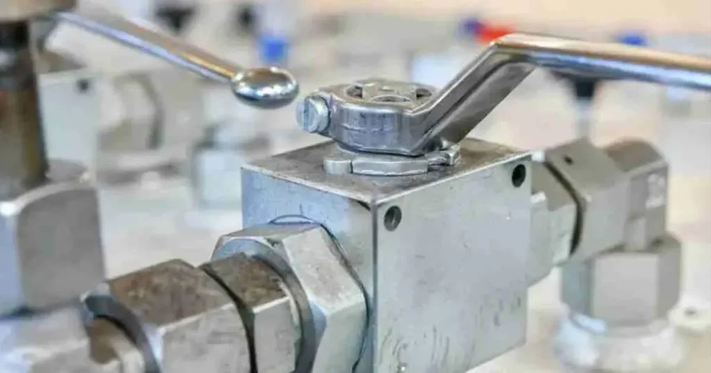
You will get to the fault faster if you describe the symptom precisely, read the circuit, compare a few measurements with a known-good condition, and isolate one section at a time. Swapping a valve before you do that may add cost while leaving the original problem in the machine.
Make the system safe before troubleshooting
Before you reach for a wrench or test hose, make the machine safe. Pressure can stay trapped after the pump stops; a suspended load can fall, an accumulator can discharge, and a loosened fitting can release a high-velocity oil jet. Follow the machine manufacturer’s lockout and stored-energy procedure for the exact equipment.
- Stop and isolate every energy source, not only the electric motor.
- Lower loads to a safe position or mechanically block them.
- Relieve trapped pressure through the designed procedure.
- Discharge and isolate accumulators.
- Confirm pressure at the relevant test point with a suitable instrument.
- Never search for a pinhole leak with your hand.
- Do not loosen a hose, plug, or valve just to check whether pressure is present.
Some readings require an energized machine. Those tests belong in a controlled procedure with guarding, rated instruments, secure connections and trained personnel outside the hazard zone.
Step 1: Describe the symptom precisely
The statement the valve does not work is too broad to diagnose. Write down what the machine actually does, when it happens, and what changed just before the problem appeared.
- Is there no movement, slow movement or movement in the wrong direction?
- Is the problem constant, intermittent, cold-start only or heat-related?
- Does it appear under load, at idle or after the valve stays in one state?
- Is there external leakage, internal drift, noise, vibration or excess temperature?
- Did it begin after maintenance, a hose change, contamination or replacement?
The timing often tells you where to look next. If the valve works with cold oil but loses control as the machine warms, internal leakage may be increasing as viscosity falls. If the fault is intermittent after a contamination event, a particle may be moving across a seat or through a close-clearance element.
Step 2: Confirm what the valve should do
Put the current schematic beside the exact valve part number before you test anything. Trace the normal state, port connections, permitted flow direction, actuation method, pilot line, spring return, and any check bypass. If you treat a normally open valve as normally closed, your measurements may be accurate while your diagnosis is completely wrong.
Use hydraulic valve symbols as a reading framework. Then confirm that the installed valve matches the drawing’s function, port arrangement, and rated direction.
Step 3: Check the system before removing the valve
| System check | Problem it can imitate | Practical verification |
|---|---|---|
| Reservoir level and suction | Slow, noisy or erratic operation | Check level, foaming, suction restriction and air entry |
| Fluid temperature and viscosity | High hot leakage or sluggish cold operation | Measure temperature and compare with the approved fluid range |
| Filter and cleanliness | Sticking, seat leakage and delay | Check indicator or differential pressure; sample fluid if needed |
| Pump flow and pressure | No flow, weak force and slow cylinders | Measure flow and pressure under a controlled load |
| Relief behavior | Low force, heat or constant bypass noise | Compare system pressure with the approved setting |
| Actuator internal leakage | Load drift blamed on a valve | Use an approved cylinder or motor isolation test |
| Electrical or pilot command | Valve fails to shift | Verify voltage/current, connector, coil, pilot pressure or linkage |
| Hoses, fittings and return path | High Δp, heat and slow response | Inspect routing; measure pressure at both ends under flow |
Tip: Record the original relief or flow setting before you touch it. Turning an adjustment until the symptom disappears can hide the evidence, overspeed the actuator, or expose the circuit to damaging pressure.
Step 4: Measure pressure and flow at meaningful points
A gauge at the pump tells you supply pressure, but it does not tell you what the valve is doing. Reproduce the fault under a controlled condition, then measure pressure immediately upstream and downstream and record the actual flow. The difference between those two pressure readings is the valve’s pressure drop.
- Command versus state: Is the valve being told to open, close or shift?
- Inlet versus outlet: Is pressure reaching the valve, and does flow leave by the expected path?
- Fault versus baseline: What changed from known-good machine behavior?
Record oil temperature with every important reading. A pressure-drop or leakage result at 25 °C is not directly comparable with one at 70 °C because viscosity and internal leakage change as the oil warms.
Hydraulic valve symptom chart
| Symptom | Possible valve causes | Check outside the valve first |
|---|---|---|
| No downstream flow | Closed shut-off valve, stuck element, blocked orifice, wrong direction or actuator not shifting | Pump output, relief bypass, command, blocked hose or disconnected coupling |
| Flow too low | Small restriction, incomplete shift, damaged passage or partly open check | Low pump flow, clogged filter, suction aeration, cold oil or undersized line |
| Actuator too fast | Throttle too open, wrong meter-in/out arrangement or reversed bypass check | Changed pump flow, load or control signal |
| External leak | Damaged stem/body/plug seal, cracked body or loose interface | Overpressure, side load, pipe strain, incompatible seal/fluid or poor mounting |
| Load drifts closed | Seat leakage, spool clearance, particle or worn seat | Cylinder piston leakage, hose expansion, thermal pressure or circuit design |
| Sticks intermittently | Contamination, burr, distortion, corrosion, swollen seal or spring damage | Wrong voltage, low pilot pressure, linkage or high-viscosity fluid |
| High local heat | Excessive Δp, partial opening, continuous throttling or internal leakage | Relief bypass, undersized lines, pump inefficiency or duty cycle |
| Noise or chatter | Unstable poppet, cavitation, flow force or damaged spring | Aeration, pump cavitation, load change, pressure pulsation or mounting |
| High operating torque | Contamination, damaged seat, pressure load, corrosion or distorted stem | Actuator sizing, linkage alignment, overpressure or pipe load |
| Check-valve reverse leak | Particle, damaged ball/poppet/seat, spring fault or wrong direction | Pressure spikes, contamination and leakage expectation |
Troubleshooting common Chenyang valve categories
Hydraulic ball valve will not open or close
If a ball valve is hard to turn, confirm pressure, alignment, and full actuator travel before you add force. A longer handle can damage the stem while hiding the actual fault.
If torque rises, compare actual line pressure with the rating and operating condition. Look for pipe strain or misalignment. After safe removal, contamination around the ball and seat may explain stiffness, but do not scratch a sealing surface while cleaning. A damaged stem, seat or body is a replacement decision, not a reason to use a longer handle.
For routine care, see ball valve maintenance. For selection, review the hydraulic ball valve range.
Hydraulic check valve leaks backward
If a load drifts, first confirm the check valve arrow and the actual pressure direction. Then measure reverse leakage at a stated pressure and oil temperature. Do not condemn the valve from cylinder movement alone; a leaking piston seal or another parallel path can produce the same drift.
Note: If the check valve is part of a safety-critical load-holding circuit, stop the machine until the complete holding circuit has been evaluated. Repeatedly slamming the valve open can worsen seat damage.
Check the intended function on the hydraulic check valve page.
Throttle or flow-control valve cannot hold speed
If your actuator speed changes with the load, check what type of valve is actually installed. A basic throttle sets an opening, so its flow changes with pressure differential and oil viscosity. A pressure-compensated flow control is designed to reduce that variation, but only within its specified operating range.
Record the adjustment, then measure flow and Δp in the metered direction. If it is one-way, test the return direction separately because the check path may provide free flow. Inspect for a blocked metering edge, loose adjustment or reversed installation.
Compare the circuit with Chenyang’s hydraulic throttle valves and hydraulic flow-control valves.
How to read pressure, flow and leakage together
| Observed pattern | Diagnostic direction |
|---|---|
| Normal upstream pressure, high Δp, low downstream flow | Restriction, partial opening, blocked path or undersized valve/line |
| Low upstream pressure and low flow | Look upstream at pump, suction, drive, relief bypass or supply control |
| Normal supply, command present, no state change | Check actuator/coil/pilot and mechanical sticking |
| Closed state, measurable downstream flow | Internal valve leakage or a parallel path |
| Load drifts but isolated valve leakage is acceptable | Check actuator sealing, circuit layout and thermal effects |
| Δp changes after warm-up at the same flow | Check actual valve position, compensation, contamination and measurement points |
When should you remove the valve?
Remove the valve only after your circuit checks show that the fault follows it, or when visible damage makes further operation unsafe. Before removal, photograph the orientation, mark every port, record each setting, clean the surrounding area, and prepare clean caps. New dirt introduced here can hide the original failure and damage the replacement.
On the bench, inspect against an approved drawing or service procedure. Look for contamination, scoring, corrosion, damaged seals, broken springs, deformed parts and abnormal wear. Do not polish a precision spool, lap a seat or substitute seal material unless the manufacturer authorizes it.
Repair or replace?
- Clean and retest when contamination is removable, no critical surface is damaged and the procedure permits service.
- Replace approved seals only with the correct material, dimensions, backup arrangement and instructions.
- Replace the valve when the body is cracked, a critical seat/bore is damaged, the control element is deformed or repair cannot be verified.
- Escalate the design when the valve works as designed but the application needs lower leakage, different fail behavior, steadier flow or lower pressure drop.
Post-repair verification
A valve that moves freely by hand has not yet proved that it will work under pressure. Flush the affected circuit, reconnect every port correctly, restore the documented settings, and run suitable hydraulic valve testing. Start at a controlled pressure and load, then watch for leakage, temperature rise, noise, and actuator behavior before returning the machine to service.
FAQ
How do I know whether a hydraulic valve is bad?
Confirm the intended state, verify the command, measure upstream/downstream pressure and flow, and isolate competing leakage paths. A fault that follows the valve under controlled testing is stronger evidence than a machine symptom alone.
Why does a valve work cold but fail hot?
As oil warms, viscosity falls and clearance leakage can rise. Thermal expansion, coil temperature, contamination and seal condition can also affect behavior. Record temperature with every observation.
Can dirty oil make a valve stick?
Yes. Particles can jam close-clearance components, damage a seat or block an orifice. ISO 4406 expresses contamination levels, while the system requirement defines the acceptable target.
Why is my check valve leaking?
Possible causes include wrong direction, a particle, damaged sealing surfaces, a spring problem or leakage elsewhere in the load circuit. Measure the valve separately before condemning it.
Why is a throttle valve not keeping constant speed?
A simple throttle’s flow changes with pressure differential and viscosity. If load or temperature changes, speed can change at the same setting. You may need pressure compensation or a different circuit.