
The valve still opens, so it is easy to assume everything is fine. Then the stroke takes half a second longer, the end-position signal arrives late, or the actuator starts hissing after it stops. Those small changes are often the best time to act. Waiting until the valve stalls turns a short inspection into an unplanned shutdown.
Pneumatic ball valve maintenance covers three connected systems: the process or hydraulic ball valve, the pneumatic actuator and air supply, and the controls that command and confirm movement. Check them separately before replacing parts. A valve can be mechanically sound while wet plant air makes the actuator slow, or the actuator can work correctly while a damaged seat causes internal leakage.
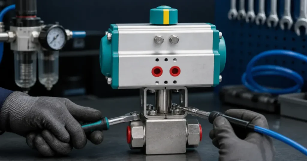
Begin with a safe maintenance state
A pneumatic actuator can move without warning if compressed air, a control signal, a spring-return mechanism, or trapped process pressure remains available. Before touching the assembly, follow the machine’s approved isolation procedure.
- Stop the process and identify what the valve isolates.
- Lock out the energy sources that can command or move the valve.
- Isolate the compressed-air supply and vent pressure from both actuator chambers and accessories.
- Isolate the fluid line and release trapped pressure on both sides of the closed ball.
- Confirm zero energy with appropriate gauges and an approved test method.
- Account for spring force, gravity loads, accumulators, hot fluid, and hazardous media.
- Mark the valve, actuator, coupling, and mounting orientation before removal.
Note: Closing a ball valve does not prove that its body cavity or downstream line is depressurized. Verify every trapped-pressure zone before loosening a tube, flange, actuator, or body fastener.
Internal actuator work should follow the exact manufacturer’s service manual. A spring-return actuator can contain dangerous stored mechanical energy even after air is removed. If the design is unknown, do not disassemble it.
Build a baseline before you set a maintenance interval
There is no honest universal rule such as “service every six months.” A valve cycling twice a day in a clean indoor power unit does not age like one cycling every few seconds beside a washdown line. Start with the manufacturer’s instructions, then adjust the inspection interval from actual duty and condition.
| Duty factor | Why it changes maintenance | Useful condition to track |
|---|---|---|
| Cycle count | Seals, bearings, coupling, and valve seats accumulate movement | Total cycles and cycles per shift |
| Long idle periods | Corrosion, seal adhesion, and contaminated air can cause breakaway problems | Time since last full stroke |
| Dirty or wet air | Water and particles damage pneumatic seals and small control passages | Filter condition, condensate, and pressure at the actuator |
| Cold or hot environment | Seal friction and material properties change | Stroke time at startup and normal temperature |
| High process pressure | Ball valve operating torque may rise with seat load | Travel time and minimum air pressure under load |
| Vibration or hose movement | Fasteners, tubing, switches, and brackets can loosen or fatigue | Movement marks, loose hardware, and intermittent signals |
| Contaminated hydraulic fluid | Particles can score seats and increase valve torque | Leakage, oil cleanliness, and torque trend |
Record the new or known-good condition: supply pressure while moving, open and close times, exhaust sound, end-position indication, external leakage, and process shut-off result. Trend against that baseline. A change is often more useful than a generic limit taken from another actuator.
A practical inspection route
Walk the system from the air source to the process valve. This order prevents you from removing the actuator when the real restriction sits in a filter, regulator, tube, or solenoid.
1. Check the air supply under flow
A static gauge can look normal while pressure collapses as soon as the actuator consumes air. Cycle the valve and watch pressure near the actuator inlet. If it drops sharply, inspect the regulator setting, filter element, undersized tubing, clogged silencers, frozen water, closed isolation valve, and air demand from other equipment.
Air should meet the actuator manufacturer’s cleanliness, dryness, and lubrication requirements. Do not assume every actuator needs an airline lubricator. Some are supplied with long-life internal lubrication and can be damaged or contaminated by an incompatible oil. Follow the actuator data sheet.
2. Listen and test for pneumatic leakage
A brief exhaust during movement is normal for a double-acting actuator. Continuous flow from a port after the actuator has stopped can indicate tubing leakage, a leaking solenoid, damaged piston seals, or a control circuit that never fully shifts.
Use an approved leak-detection method at fittings and covers. Do not tighten fittings blindly while the system is energized. A cracked tube, damaged thread, or misassembled push-in fitting may need replacement rather than more torque.
3. Compare open and close stroke
Measure both directions. If only one direction slows, the cause may be a restricted control path, blocked exhaust, asymmetric mechanical load, or leakage in one actuator chamber. If both slow equally, low supply pressure, dirty air, a binding valve, or a general exhaust restriction becomes more likely.
Check the physical position indicator as well as the control-system feedback. A limit switch can report the wrong position if its cam moved. The valve can also reach an end stop while the ball is not correctly aligned because the coupling slipped.
4. Inspect the mounting and coupling
Look for loose bracket bolts, fretting marks, cracked brackets, shaft play, and movement between the actuator and valve. The actuator output shaft and valve stem should share the intended axis. Misalignment adds side load, raises torque, and wears the coupling and stem.
Do not compensate for a binding valve by increasing supply pressure without checking the actuator and valve ratings. Extra actuator torque can damage the stem, stop, coupling, or seats.
5. Inspect the process valve
Check the valve body, end connections, stem area, and joint faces for external leakage or corrosion. A stain can come from the line fitting rather than the valve stem, so clean the area and identify the first wet point.
For internal shut-off leakage, isolate the downstream volume and use the approved test method. Falling downstream pressure may also come from another valve, a cylinder seal, or trapped-temperature change. Do not diagnose the ball seats from one gauge without isolating other leakage paths.
The article on hydraulic ball valve leakage separates connection, stem, body, and internal seat leakage so you can start at the right location.
Maintenance checklist by component
| Component | Check | Act when you find |
|---|---|---|
| Air filter and regulator | Pressure under flow, condensate, filter restriction, damaged bowl | Unstable pressure, water, contamination, or physical damage |
| Air tubing and fittings | Kinks, abrasion, heat damage, loose support, leakage | Pressure loss, rubbing, hardened tube, or cracked fitting |
| Solenoid and exhaust | Correct command, manual override state, coil condition, blocked silencer | Late shifting, overheating, contamination, or restricted exhaust |
| Actuator body | Corrosion, dents, loose end caps, continuous leakage | Damage, seal leakage, or unsafe hardware condition |
| Travel stops and indicator | Full 0° and 90° movement as specified, secure adjustments | Overtravel, undertravel, or feedback disagreement |
| Bracket and coupling | Alignment, fasteners, play, cracks, slipped position | Side load, looseness, fretting, or incomplete stem travel |
| Valve body and connections | External leakage, corrosion, mounting stress | Wet joint, damaged surface, pipe strain, or loose support |
| Ball, seats, stem, and seals | Operating torque, shut-off leakage, stem leakage | Rising torque, scoring, swelling, wear, or persistent leakage |
| Limit switches or sensors | Signal at actual end positions, cable and enclosure condition | False feedback, intermittent contact, moisture, or loose cam |
Do you need to lubricate a pneumatic ball valve?
Only if the manufacturer’s instructions provide a lubrication point, lubricant type, amount, and interval. Many soft-seated ball valves and rack-and-pinion actuators are assembled with compatible lubricant for their intended service. Adding a random grease can swell elastomers, contaminate hydraulic fluid, collect particles, block small air passages, or make operating torque less predictable.
Before adding lubricant, confirm:
- The valve or actuator is designed for field lubrication
- The lubricant is compatible with the fluid, seats, O-rings, actuator seals, and temperature
- The existing lubricant and new product can be mixed
- The specified quantity and application point
- Whether the line must be cleaned afterward
If the manual does not state a lubrication procedure, cleaning and diagnosis are safer than guessing.
How to separate actuator trouble from valve trouble
After safe isolation and only when the service procedure permits separation, compare the actuator and valve independently.
| Observation | More likely area | Next check |
|---|---|---|
| Valve stem turns smoothly by the approved manual method, actuator will not travel | Air supply, solenoid, actuator, or coupling | Pressure under flow, exhaust, actuator seals, and output motion |
| Actuator strokes normally off the valve, valve stem is hard to turn | Ball valve, fluid contamination, pressure load, seats, or stem | Depressurized valve torque, cleanliness, internal condition |
| Both move separately but bind when assembled | Bracket, coupling, shaft alignment, or incorrect mounting position | Concentricity, coupling engagement, and bolt sequence |
| Actuator completes travel but valve leaks internally | Incorrect ball position, seat damage, debris, or pressure-direction effect | Stop setting, coupling slip, seat test, and valve design |
| PLC feedback changes but physical indicator does not | Switch cam, wiring logic, or feedback device | Compare electrical signal with actual shaft position |
If the assembly has repeated faults, the pneumatic ball valve replacement decision should compare repair cost with valve condition, actuator compatibility, downtime, available spare kits, and the risk of another shutdown.
Condition-based actions for common symptoms
Stroke time is increasing. Check dynamic air pressure, filter restriction, silencers, tubing, temperature, and valve torque. Record separate open and close times.
The actuator stops halfway. Isolate safely, then verify air pressure, solenoid position, coupling, stop settings, and mechanical resistance. Do not repeatedly hammer the valve with higher pressure.
Air leaks continuously. Identify whether it comes from a fitting, solenoid exhaust, shaft seal, or actuator cover. Internal piston leakage may vent through the opposite port and requires the actuator-specific service procedure.
The valve leaks fluid externally. Find the first wet location. A connection leak needs a different repair from a stem or body-joint leak.
The valve no longer shuts off. Confirm full travel, correct coupling position, pressure direction, fluid cleanliness, and seat condition. A closed-position switch does not prove seat tightness.
Operation changes only when cold. Check oil viscosity, pneumatic seal friction, condensate freezing, regulator behavior, and available actuator torque at the actual supply pressure.
Recommissioning after maintenance
- Confirm all tools, plugs, temporary caps, and loose parts are removed.
- Verify bracket, coupling, stops, tubing, sensors, and guards against the approved drawing.
- Restore the air supply gradually and check for leakage.
- Cycle the valve at no process pressure if the system procedure permits it.
- Confirm physical open and closed positions and compare them with electrical feedback.
- Restore process pressure in a controlled way and inspect external joints.
- Measure stroke time and shut-off performance under representative load.
- Record the new baseline, parts replaced, settings, and next inspection trigger.
A maintenance record should contain measurements, not only “checked OK.” Supply pressure during travel, open and close time, leakage result, cycle count, temperature, and replaced seal-kit number give the next technician something useful to compare.
What to prepare for spare parts or replacement
Record the complete valve and actuator model, double-acting or spring-return function, fail position, available air pressure, valve breakaway torque requirement, mounting pattern, shaft and coupling dimensions, hydraulic pressure, fluid, temperature, port standard, cycle duty, and control accessories.
Chenyang’s KHB/KHM pneumatic hydraulic ball valve range currently identifies double-acting actuators on the published models. Confirm the exact model and actuator size before ordering seals, a replacement actuator, or a complete assembly; do not apply one maintenance procedure to every pneumatic design.
FAQ
How often should a pneumatic ball valve be maintained?
Use the manufacturer’s minimum requirement, then adjust from cycle count, environment, air quality, process pressure, temperature, leakage trend, and criticality. Track changes in stroke time and air leakage rather than relying on one calendar interval for every valve.
What causes a pneumatic ball valve to move slowly?
Common causes include low dynamic air pressure, clogged filters or silencers, undersized tubing, solenoid restriction, cold seals, internal actuator leakage, misalignment, and rising ball-valve torque.
Should a pneumatic actuator exhaust air when it stops?
A brief exhaust during movement is expected. Continuous exhaust after travel can indicate a leaking control valve, incomplete shifting, tubing fault, or internal actuator-seal leakage, depending on the circuit.
Can I increase air pressure if the valve sticks?
Not until you identify the cause and verify all ratings. Higher pressure can overload the actuator, coupling, valve stem, travel stops, or seats. Check supply restriction, alignment, contamination, and valve torque first.
Can I maintain the actuator without removing the valve?
Some external checks can be done in place after safe isolation. Internal repair depends on the actuator design and manufacturer instructions. Spring-return units contain stored energy and require trained service procedures.