Hydraulic valve symbols describe function, not the physical shape of a valve. A small group of lines, boxes, arrows, springs, and port labels can tell you where the oil can flow, which path is blocked, how the valve shifts, and what happens when the control signal disappears. Once you read those elements in the right order, a complicated symbol becomes much easier to understand.
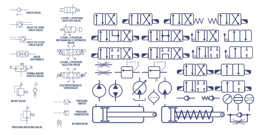
The main reference is ISO 1219-1, which establishes the basic elements and rules used to build fluid-power symbols. The symbol on a machine drawing may look slightly different from the one in a catalog, but its functional logic should remain consistent.
Start with function, not the valve name
Before you try to name a symbol, ask three questions: Does it select a flow path, limit pressure, or meter flow? Those functions place most hydraulic valves into directional, pressure-control, or flow-control families. Check valves and shut-off valves also control direction, but their symbols are much simpler than a multi-position spool valve.
This distinction matters when you move from a drawing to a real component. A symbol may show that a line is isolated, but it does not tell you the body material, pressure rating, thread standard, seal compound, or allowable leakage. You still need the valve data sheet for those details.
A five-step method for reading hydraulic valve symbols
1. Count the position boxes
Directional valve symbols use one adjacent square for each operating position. A two-position valve has two boxes. A three-position valve has three. The boxes are not separate physical valves; they show the possible internal flow states of one valve.
The number of ports and positions is commonly written as 2/2, 3/2, 4/2, or 4/3. The first number is the number of main ports. The second is the number of positions. A 4/3 valve therefore has four main ports and three operating positions.
2. Read the flow paths inside one box at a time
An arrow inside a box shows a permitted connection and the functional direction of flow. A line ending against a short bar shows a blocked port. A joined line shows that two ports communicate in that position.
Do not read all adjacent boxes as if they operate at the same time. Pick the current position first, then follow only the paths drawn inside that box.
3. Identify the normal or rest position
A spring drawn at one end normally pushes the valve toward the box next to that spring. That adjacent box represents the spring-return state when the opposing force is absent. With a spring on each end of a three-position valve, the center box is normally the neutral state.
This is one of the most common reading errors. People often begin with the left-hand box because it appears first on the page. The correct starting point comes from the spring and actuator arrangement, not the reading direction of the text.
4. Decode the actuators
Symbols attached to the ends show what moves the valve: a hand lever, push button, roller, mechanical linkage, hydraulic pilot, pneumatic pilot, or solenoid. A symbol can have different operators on opposite ends, such as a solenoid for shifting and a spring for returning.
The actuator tells you how the state changes. It does not change the meaning of the internal flow paths. Read the boxes first, then use the actuator to determine when each box becomes active.
5. Follow the ports into the circuit
Port labels tell you where the valve connects. On many hydraulic drawings, P is the pressure supply, T is the tank return, and A and B are work ports leading to an actuator. X and Y often identify pilot supply and pilot drain connections. L may identify a leakage or case-drain path, depending on the component and drawing convention.
| Typical label | Usual function | What you should verify |
|---|---|---|
| P | Pressure or pump supply | Available pressure and flow at the valve inlet |
| T | Return to tank | Back pressure and return-line restriction |
| A, B | Working ports | Which actuator chamber or motor port each line serves |
| X | External pilot supply | Required pilot pressure and source |
| Y | External pilot drain | Allowable drain pressure and correct tank routing |
| L | Leakage or case drain | The component manufacturer?s exact definition |
Common hydraulic valve symbol families
| Valve family | Main symbol clue | Function shown | What the symbol does not prove |
|---|---|---|---|
| Shut-off valve | Open or blocked two-port path | Isolates a hydraulic line | Pressure rating, seat material, or zero-leakage performance |
| Check valve | One-way closure element against a seat | Allows forward flow and blocks reverse flow | Cracking pressure or suitability for load holding |
| Directional control valve | Two or more position boxes | Starts, stops, or redirects flow between ports | Spool geometry, rated flow, leakage, or response time |
| Pressure-control valve | Spring-loaded control path with pressure sensing | Limits, reduces, sequences, or unloads pressure | Factory setting, override curve, or stability |
| Throttle or restrictor | Restriction symbol; diagonal arrow if adjustable | Changes the available flow area | Constant flow under changing load |
| Pressure-compensated flow control | Restrictor combined with a compensating element | Reduces flow variation as load pressure changes | Accuracy across all viscosity and temperature conditions |
How shut-off, check, and throttle symbols relate to real hardware
A functional symbol gives you the operating principle, while the real valve design determines pressure capability, leakage, and service life. A hydraulic ball valve symbol, for example, shows a quarter-turn isolation function. It does not show whether the valve body is carbon steel or stainless steel, whether the connection is NPT or BSP, or whether the ball uses a particular seat material.
A hydraulic check valve symbol shows permitted flow and blocked reverse flow. The actual opening point depends on spring force, effective area, friction, and inlet pressure. A standard inline check valve also should not be treated as a certified load-holding valve unless the circuit design and valve documentation support that duty.
A throttle symbol represents a restriction. Add a diagonal arrow and the restriction is adjustable. Put a check valve in parallel and you have one-direction metering with freer reverse flow. This is the functional idea behind many one-way speed controls, including designs discussed on Chenyang?s hydraulic flow control valve page.
Four practical reading examples
A two-port shut-off valve
If one state connects the two ports and the other blocks the path, the valve provides an on/off function. The symbol tells you which control action opens or closes the path. For a manually operated hydraulic ball valve, the physical handle position must still be checked against the product marking and installation instructions. Chenyang?s separate explanation of the hydraulic shut-off valve symbol goes deeper into that function.
A spring-loaded check valve
The closure element is pushed toward its seat by a spring. Forward pressure must create enough force to overcome the spring and any friction before the valve begins to open. Reverse pressure pushes the element toward the seat. The symbol shows that operating logic, but the data sheet must provide cracking pressure and leakage limits.
An adjustable throttle with reverse check
Trace both parallel paths. In the metered direction, the check valve closes and oil passes through the adjustable restriction. In the reverse direction, the check opens and bypasses the restriction. If you read only the throttle branch, you may wrongly assume the valve restricts both directions.
A 4/3 directional valve
First locate the center state from the springs. Then trace P, T, A, and B in the center box. A closed center blocks all four ports; an open or tandem center connects some ports while blocking others. Next, read each shifted box to see which work port receives pressure and which returns to tank. Never identify the center condition from the words ?4/3 valve? alone.
Simplified and detailed symbols are both valid
A simplified symbol communicates the component?s overall function. A detailed symbol may expose internal pilots, compensators, drains, check elements, and restrictors. The simplified version is easier to scan in a large circuit. The detailed version is more useful when you need to understand behavior, adjust the circuit, or diagnose an unexpected pressure path.
Do not assume the detailed drawing is a literal cross-section. ISO fluid-power symbols remain functional representations. The physical passages inside the manufactured valve may be arranged differently.
Mistakes that cause wrong diagnoses
- Reading the left-hand box as the normal state without checking the spring.
- Confusing port count with position count.
- Assuming every arrow represents the flow that is occurring right now.
- Missing an external pilot or drain line.
- Reading a parallel check valve as a series component.
- Assuming an adjustable restriction is automatically pressure compensated.
- Using the symbol as proof of pressure rating, leakage class, connection standard, or material.
- Mixing a hydraulic circuit symbol with a process-industry P&ID symbol.
Turn the schematic into a valve specification
Once you understand the symbol, translate it into purchasing data. Record the valve function, normal state, number of ports and positions, actuation method, required flow path, working and peak pressure, target flow, allowable pressure drop, port standard, fluid, temperature, leakage requirement, and installation limits.
For a Chenyang shut-off, check, throttle, or flow-control application, send the schematic together with those operating details. A cropped symbol without the surrounding circuit is rarely enough because the adjacent lines show load direction, return pressure, pilot routing, and whether the valve is being asked to meter or isolate flow.
FAQ
Are hydraulic valve symbols standardized?
ISO 1219-1 provides the main international rules for fluid-power symbols. Older drawings and manufacturer-specific documents may use variants, so check the drawing legend when a symbol differs from the current convention.
What do P, T, A, and B mean on a hydraulic valve?
P normally identifies pressure supply, T identifies tank return, and A and B are work ports. Confirm the component drawing because special valves may use additional labels or different port assignments.
How do you find the normal position of a hydraulic valve?
Look at the spring or other biasing element. The box adjacent to the spring normally shows the state held by that spring when the opposing actuator or pilot signal is absent.
Does an arrow through a restriction mean pressure compensation?
No. A diagonal arrow usually means the restriction is adjustable. Pressure compensation requires an additional compensating function in the symbol and in the physical valve.
Can a check valve symbol confirm safe load holding?
No. A basic check valve blocks reverse flow, but safe load holding may require a pilot-operated check valve, counterbalance valve, redundant protection, or another circuit-specific solution. Verify the machine risk assessment and component documentation.
Need help matching a symbol to a real valve?
Send Chenyang Hydraulic the complete circuit section, operating pressure, peak pressure, required flow, port standard, fluid, temperature, and installation constraints. We can review whether a ball valve, inline check valve, throttle valve, or flow-control product matches the function shown. Contact Chenyang Hydraulic with your drawing and required quantity.