
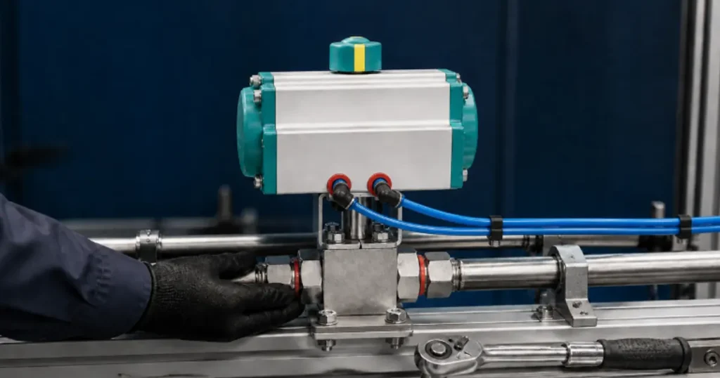
You connect the air lines, send an open command, and the actuator moves. That does not yet prove the installation is correct. A slipped coupling can give you a 90-degree actuator stroke without a fully open ball. Pipe strain can make a new valve hard to turn. A small exhaust restriction can slow closing enough to upset the machine sequence.
A reliable pneumatic ball valve installation has to align four things: the valve with the hydraulic line, the actuator with the valve stem, the air circuit with the actuator function, and the feedback signal with the ball’s real position. Treat commissioning as part of installation, not as a quick check after the mechanics are finished.
Confirm the assembly before it reaches the machine
Start with the order and drawing, not the air fittings. Verify that the complete valve and actuator assembly matches the duty.
| Item to confirm | Why it matters |
|---|---|
| Valve model and nominal size | The connection can fit while the bore or flow capacity is wrong |
| Maximum working and peak pressure | The valve body and connections must suit both steady and transient pressure |
| Fluid and temperature | They affect body, seat, O-ring, and lubricant compatibility |
| Port or flange standard | NPT, BSP, metric, SAE, and flange interfaces are not identified by diameter alone |
| Valve operating torque | The actuator must deliver enough torque at the lowest available air pressure |
| Actuator function | Double-acting and spring-return units use different air circuits and loss-of-air behavior |
| Fail position | The required machine state after loss of air or power must be known before tubing and controls are connected |
| Mounting and coupling dimensions | Poor engagement or offset loading can damage the stem and bracket |
| Accessories and signals | Solenoid, speed controls, limit switches, and position indicators must match the control system |
Actuator torque data is normally tied to supply pressure and stroke direction. If plant pressure falls while several devices move, size against the pressure available at the actuator during the worst case—not the unloaded compressor setting.
Put the system in a safe installation state
Follow the machine’s approved lockout and isolation procedure. The hydraulic or process line must be shut down, isolated, drained where required, and confirmed depressurized. Isolate compressed air and electrical control power. Secure any load that could move when the line is opened.
If an actuator is already attached, do not use it as a lifting eye unless the manufacturer has provided an approved lifting point. Support the assembly by its intended structural points. Protect the indicator, solenoid, tubing fittings, and switch box from impact.
Note: A spring-return actuator can rotate when air is removed. A double-acting actuator may still contain trapped air. Keep hands and tools away from the coupling and travel stops until every energy source is controlled.
Inspect the valve and actuator before installation
- Compare model markings with the purchase order and drawing.
- Check the valve body, actuator housing, bracket, coupling, ports, cable entries, and air fittings for transport damage.
- Remove protective caps only when you are ready to connect the clean line.
- Inspect the valve bore and ports for plugs, packaging, chips, corrosion inhibitor buildup, or foreign material.
- Confirm the actuator indicator agrees with the valve position.
- Check that mounting bolts and travel-stop locknuts are secure according to the supplied procedure.
- Verify that seals, gaskets, clamps, and fasteners match the selected connection.
If the assembled valve can be safely cycled on a controlled bench according to its instructions, verify full movement before it enters the line. Stop if you hear scraping, see bracket movement, or find a disagreement between the indicator and actual flow path.
Prepare and align the hydraulic line
Flush or clean the line before installing the valve. Welding slag, thread chips, abrasive, and sealant fragments can score a ball seat on the first cycle. Deburr pipe or tube ends and keep protective caps in place until final assembly.
The line should meet the valve without being forced sideways or pulled into length by the connection. Support heavy hoses and pipes independently. Pipe strain can distort a compact valve body or side-load the stem, which shows up as high actuator torque even though the valve was free on the bench.
Leave enough clearance to remove the actuator, bracket, air fittings, and valve later. An installation that works only until the first seal change is not finished.
Install the valve connection correctly
Threaded connections
Confirm the exact thread standard and sealing method. NPT is not BSPT, and a parallel thread may seal on an O-ring or bonded washer rather than on the thread. Do not judge thread type from outside diameter alone.
Apply only the specified sealant and keep it away from the first internal thread and flow passage. Hold the valve at its wrench flats. Do not apply installation torque through the actuator, bracket, or valve stem. Excess torque can distort the body; insufficient engagement or incompatible threads can leak.
SAE and other flanged connections
Check code, nominal size, bolt pattern, flange-head dimensions, O-ring, and hardware. Clean the port face and groove. Bring the flanged head squarely into position, then tighten the correct fasteners gradually in a cross pattern using the controlled torque procedure.
Do not mix Code 61 and Code 62 clamps or use the bolts to correct line misalignment. Chenyang’s SAE flanged high-pressure ball valve models publish separate dimensions for the F3 and F6 connection families.
Flow direction and orientation
Many two-way ball valves are bidirectional for isolation, but not every valve assembly, cavity-relief arrangement, seat design, or accessory is direction-independent. Follow the product arrow or drawing when one is provided.
Choose an orientation that keeps the actuator supported and serviceable. Avoid placing electrical or pneumatic accessories where water, heat, falling debris, or mechanical impact can collect. If the actuator orientation changes from the approved assembly, confirm whether the bracket load, indicator, drainage, and service access remain acceptable.
Mounting an actuator to a separate ball valve
If you receive a factory-assembled unit, leave the actuator-valve alignment intact unless the installation requires removal. When a separate actuator must be mounted, use the valve and actuator instructions together.
- Put the valve in the specified open or closed reference position.
- Put the actuator in the corresponding position and confirm its rotation direction.
- Install the correct bracket and coupling without forcing the parts together.
- Check coupling engagement on both shafts. Too little engagement can strip the drive; bottoming can apply axial load.
- Align the actuator output shaft with the valve stem before tightening the bracket.
- Tighten mounting hardware in stages using the specified values.
- Cycle slowly and watch for bracket movement, stem side load, or coupling slip.
Before commissioning your actuator-valve assembly, confirm that the valve reaches its intended fully open and fully closed positions, then follow the installation procedure for the exact valve and actuator model. Use only the specified mounting hardware, tightening values, travel-stop settings, and air-pressure limits. Do not copy these settings from a different assembly, even when the products look similar.
Connect the compressed-air circuit
Clean, dry air at stable pressure is the starting point. The required cleanliness class, dew point, lubrication condition, and allowable pressure must come from the actuator and accessory data.
For a double-acting actuator, air drives both opening and closing. Identify which port produces each direction before connecting the control valve. Reversed tubes can make the control-system command opposite to the physical result.
For a spring-return actuator, air drives one direction and the spring drives the fail direction. Confirm whether loss of air must open or close the ball, then verify the installed orientation actually delivers that state.
Keep tubing short enough to avoid unnecessary delay but long enough to permit service without pulling on fittings. Protect it from abrasion, hot surfaces, sharp edges, and moving parts. Size the tube, fittings, solenoid path, and exhaust for the required actuator volume and stroke time.
If speed controls are used, adjust them according to the pneumatic circuit design. Restricting exhaust is common in actuator speed control, but the correct arrangement depends on the accessory. A blocked silencer can behave like an unintended restriction and make the valve stop short.
Wire controls and position feedback
If the system includes a solenoid or limit-switch box, qualified personnel should wire it to the supplied diagram and applicable electrical rules. Verify voltage, power, enclosure rating, grounding, cable gland, and hazardous-area requirements where relevant.
Do not treat the feedback switch as proof of valve position until it has been calibrated against physical travel. Set the open signal when the ball is fully open, and the closed signal when it reaches the correct closed position. Leave enough margin for repeatable switching without hiding undertravel.
The solenoid valve is part of the machine’s control system; this article does not imply that Chenyang supplies solenoids or electrical accessories with every pneumatic ball valve.
Set travel stops without overdriving the valve
A quarter-turn ball valve normally moves between fully open and fully closed positions. The actuator stops should let the ball reach those positions without applying unnecessary force after the valve has seated.
Check:
- The ball bore aligns with the valve passage when open
- The closed position blocks the passage as designed
- The actuator does not hit its internal stop before the valve reaches position
- The valve is not being overdriven beyond its mechanical travel
- The position indicator and switches agree with physical position
If the actuator reaches 90 degrees but the valve leaks through, inspect coupling orientation, slip, ball position, debris, and seat condition. More closing torque is not automatically the answer.
Commission the installation in stages
- Static inspection. Confirm every mechanical, pneumatic, and electrical connection against the drawing.
- Low-energy air test. Restore air in a controlled way, check leakage, and verify the intended rotation direction.
- Dry functional cycle. If permitted by the valve procedure, cycle several times without process pressure and measure open and close times.
- Feedback test. Compare indicator, switch signals, control-system status, and actual valve position.
- Controlled process pressurization. Introduce hydraulic or process pressure gradually while checking body, stem, threads, and flanges.
- Loaded cycle test. Operate under representative differential pressure and confirm complete travel without abnormal noise or delay.
- Shut-off verification. Test internal leakage with the approved method when the application requires it.
- Loss-of-energy test. Verify the intended response to loss of air or control power when the machine safety procedure permits the test.
- Record the baseline. Save dynamic air pressure, stroke times, leakage results, stop positions, and control settings.
Do not jump from a no-load air cycle to full system pressure without an intermediate inspection. A small alignment or sealing error is easier to contain before the line reaches normal energy.
Common installation problems and where to look
| Symptom during commissioning | Likely installation causes | First checks |
|---|---|---|
| Actuator does not move | No air, wrong solenoid state, blocked port, incorrect tubing | Supply pressure, isolation valves, command, manual override, tube routing |
| Moves in the wrong direction | Actuator ports reversed or control logic inverted | Port function, wiring logic, physical indicator |
| Stops before full travel | Low dynamic pressure, restricted exhaust, stop setting, coupling slip, pipe strain | Pressure during motion, silencers, stops, mounting alignment |
| Valve becomes hard to operate after piping connection | Body distortion or line misalignment | Pipe support, connection torque, flange parallelism |
| Air leaks continuously | Damaged fitting, tube, solenoid, or actuator seal | Locate exact leak before replacing the valve |
| Fluid leaks externally | Wrong seal, damaged face, mixed thread, uneven flange tightening | First wet point, seal specification, interface, assembly procedure |
| Closed signal but internal leakage remains | Incorrect switch setting, undertravel, coupling error, debris, damaged seat | Actual ball position and isolated leakage test |
| Stroke time changes when other equipment runs | Shared air supply is undersized or poorly regulated | Pressure at actuator while all expected users operate |
How this differs from installing a manual ball valve
The process connection, pressure rating, fluid compatibility, cleanliness, and alignment checks are shared with a manual valve. The pneumatic assembly adds torque matching, actuator-valve alignment, air quality, tubing capacity, control logic, travel-stop adjustment, position feedback, and loss-of-energy behavior.
Use the existing hydraulic ball valve installation guide for general thread, flange, line preparation, and leak-test principles. Use this page for the actuator and control layers. The manual versus pneumatic ball valve comparison can help if the operating method is still being selected.
Information to send before ordering
- Required valve function and normal position
- Double-acting or spring-return actuator and required fail state
- Minimum air pressure available during operation
- Required open and close time
- Hydraulic working pressure, peak pressure, and differential pressure
- Required flow and allowable pressure drop
- Fluid and temperature range
- Port size and connection standard
- Control voltage and feedback requirement, if accessories are included in the system
- Installation orientation, available envelope, and service clearance
- Machine drawing, existing model, and quantity
Chenyang’s published KHB/KHM hydraulic ball valves with pneumatic actuators use double-acting actuators on the listed configurations. Send the complete duty and interface data so the valve model, actuator size, and installation envelope can be checked together.
FAQ
Can a pneumatic ball valve be installed in any orientation?
Do not assume so. The valve may tolerate several orientations, but actuator weight, drainage, accessory protection, bracket load, service access, and manufacturer instructions still control the final position.
How much air pressure does a pneumatic ball valve need?
Use the actuator’s torque table and allowable pressure range. Size against the lowest pressure available at the actuator while it moves under the worst valve torque, not only the compressor setting.
Should I install an air lubricator?
Only when the actuator manufacturer specifies lubricated air. Many actuators use factory lubrication, and an incompatible added oil can damage seals or collect contamination.
How do I know the valve is fully open?
Check actual valve travel and bore alignment during setup, then calibrate the physical indicator and limit switch to that position. An actuator reaching its own stop does not by itself prove the ball is correctly aligned.
Can I use the actuator body to tighten a threaded valve?
No. Hold the valve at its approved wrench flats and follow the connection procedure. Torque applied through the actuator, bracket, or stem can misalign or damage the assembly.