
A 1/2-inch hydraulic valve is not automatically right for a 1/2-inch hose. The connection may fit while the internal bore is too small, the pressure drop is too high, or the reverse-flow path cannot carry the cylinder’s return flow.
Good hydraulic valve sizing starts with the circuit, not the thread. You need the valve’s function, the highest flow each port will actually see, the working and peak pressures, an allowable pressure drop, the oil’s hot and cold viscosity, and the way the load moves. Only then does the catalog size mean something.
Valve size is a performance choice, not a connection choice
Several labels get mixed together during purchasing. Nominal size describes a connection or standardized size family. Port size describes the thread or flange interface. Bore is the actual opening through the valve. Rated flow is a manufacturer’s stated flow under defined test conditions. Cv or Kv describes flow capacity using a standardized reference fluid and pressure drop.
Those values are related, but they are not interchangeable. Two valves with the same NPT port can have different bores, turns, metering edges, check elements, or pressure-drop curves. One may pass your design flow efficiently while the other consumes enough pressure to slow the actuator and heat the oil.
| Catalog item | What it tells you | What it does not prove |
|---|---|---|
| DN or nominal size | The product’s nominal connection or size family | The minimum internal opening or acceptable hydraulic loss |
| Thread or flange size | Whether the interface can connect to your line | Flow capacity, sealing compatibility, or correct thread standard |
| Maximum flow | A limit or rating under stated conditions | Your pressure drop at cold start, hot oil, or a different flow direction |
| Cv or Kv | A way to compare valve capacity under defined reference conditions | Complete behavior with viscous hydraulic oil or a partly open metering element |
| Pressure rating | Allowable pressure for a stated configuration and temperature | Proof, burst, fatigue, or safe operation outside the stated conditions |
Start by defining what the valve must do
An isolation valve, a check valve, a throttle valve, and a pressure-compensated flow control valve do different jobs. Sizing them from one generic flow rating misses the part of the design that matters most.
| Valve function | Critical sizing questions | Common sizing mistake |
|---|---|---|
| Ball or shut-off valve | Open-position pressure drop, bore, pressure at each port, shutoff direction, operating torque | Matching the port to the hose and never checking the bore |
| Throttle or needle-style restrictor | Required adjustment range, pressure drop at each setting, direction of control, heat generation | Choosing a large valve that has almost no usable adjustment at low flow |
| Pressure-compensated flow control | Regulated flow range, minimum pressure differential for regulation, reverse-flow feature, excess-flow path | Assuming every valve labeled flow control is pressure compensated |
| Check valve | Forward-flow pressure drop, cracking pressure, reverse pressure, leakage requirement, installation orientation | Using maximum flow alone and ignoring cracking pressure or reverse leakage |
| Directional valve | Highest path flow in every position, pressure drop through P-A/B-T paths, return-flow multiplication, spool function | Sizing only from pump flow even though one work port sees higher return flow |
Chenyang’s commercial range includes hydraulic ball valves, flow control valves, throttle valves, check valves, and shut-off valves. Directional and pressure-control valves may still appear elsewhere in your circuit, but they are not automatically part of Chenyang’s product scope.
Calculate the maximum flow at the valve, not only the pump
Pump delivery is a starting point. The valve may see a different flow because of cylinder area ratio, multiple functions combining, an accumulator discharging, a motor overspeeding, or a bypass path returning excess oil.
For a cylinder, the basic relationship is:
Q = A x v
Q is volumetric flow, A is the active piston area, and v is piston speed. Keep the units consistent. The same cylinder speed needs more flow on the full-bore area than on the smaller annular area around the rod.
Do not miss cylinder return-flow multiplication
During retraction, the pump feeds the rod side. Oil leaves the larger cap-end area, so cap-end return flow can be higher than pump flow:
Q_return = Q_pump x A_cap / A_annulus
Take an illustrative 80 mm bore cylinder with a 45 mm rod. The full piston area is about 5,027 mm2 and the annular area is about 3,436 mm2. If 40 L/min enters the rod end, cap-end return flow is approximately 58.5 L/min. A valve selected only for the 40 L/min pump flow can be undersized on that return path.
This is an engineering example, not Chenyang product data. Use the actual bore, rod diameter, cushioning arrangement, leakage, and speed profile for your machine.
Set an allowable pressure drop before choosing a size
A valve can pass the required flow and still be the wrong size. The missing question is how much pressure it consumes while doing so.
Measure or estimate the pressure immediately upstream and downstream of the valve at the design flow. Their difference is the valve pressure drop, delta p. That lost hydraulic power becomes heat:
Power loss (kW) = delta p (bar) x Q (L/min) / 600
If 40 L/min crosses a valve with a 10 bar drop, the hydraulic loss is about 0.67 kW. That heat does not move the cylinder or turn the motor; the cooling system has to remove it.
There is no single acceptable pressure drop for every circuit. A simple isolation valve is normally chosen for low loss when fully open. A throttle valve needs a deliberate pressure drop to meter flow. A pressure-compensated valve also needs enough differential pressure to stay in regulation. Your pressure budget must leave enough pressure for the actuator load after line, fitting, filter, and valve losses.
Use the manufacturer’s curve at the right conditions
Read the full curve, not only the bold maximum-flow number. Confirm the valve position, flow direction, oil grade, viscosity, temperature, and test pressure differential. An official pressure-compensated valve selector, for example, lists nominal flows at a stated valve pressure differential and oil condition. That is why a catalog flow value without its test condition is incomplete.
If the curve is based on thinner oil than your cold-start condition, the real pressure drop may be higher. If your flow is near the end of the curve, leave room for pump tolerance, return-flow multiplication, and transient demand rather than treating the plotted limit as a comfortable operating point.
Check pressure as a duty cycle, not one gauge reading
Write down normal working pressure, maximum load pressure, peak or transient pressure, and the pressure that can be trapped at each port. These are not the same as proof/test pressure or burst pressure.
- Working pressure is the pressure allowed during normal service under stated conditions.
- Peak pressure is a short transient that may occur during switching, impact, or load change. Its allowable magnitude and duration must come from the product documentation.
- Proof or test pressure is used for a defined verification procedure. It is not a higher operating rating.
- Burst pressure concerns pressure-boundary failure under test conditions. It is not a usable design pressure.
Also check whether all ports have the same rating. A drain, tank, pilot, or actuator port can have a lower limit than the main inlet. On a three-way ball valve, pressure may act on different cavities as the ball rotates. On a check valve, reverse pressure loads the seat even when forward-flow pressure drop is small.
Note: A relief-valve setting does not prove that every valve port stays below that pressure. Pressure intensification, trapped fluid, return-line restriction, thermal expansion, and switching transients can create different local conditions.
Temperature, viscosity, and contamination change the result
Cold oil resists flow more strongly. Hot oil is thinner and can increase internal leakage. A valve that feels correctly sized after warm-up may make the machine sluggish at start-up, while a valve selected only for cold pressure drop may offer poor low-flow adjustment when hot.
Record the hydraulic fluid, viscosity grade, realistic cold-start temperature, stabilized operating temperature, and any fire-resistant or biodegradable fluid requirement. Then verify body, seat, O-ring, backup-ring, and coating compatibility for the exact valve series.
Small metering openings are also sensitive to contamination. Sizing a larger port does not solve a contaminated compensator or needle. Use the cleanliness level, filtration, and commissioning procedure required by the selected valve. If a new component is installed after a hose or pump failure, flush the circuit before the debris reaches the new metering edge.
Match connection, bore, and installation space
Once flow and pressure are under control, confirm the mechanical fit. NPT, BSPP/G, BSPT, metric, SAE straight thread, and flange connections are not interchangeable just because their nominal sizes look similar. The guide to NPT and BSP threads shows why pitch, taper, sealing method, and gauge standard need separate checks.
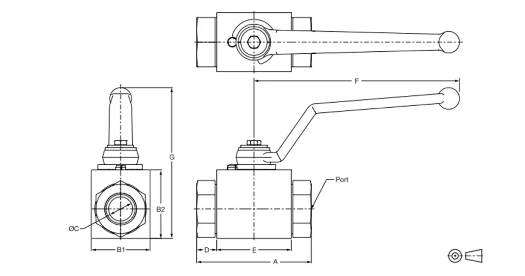
Look beyond the port: body length, handle swing, actuator envelope, hose bend radius, wrench clearance, mounting orientation, weight, and service access all affect the installed valve. A technically correct size can still be unusable if the handle hits the machine frame or the hose side-loads the body.
Use this sizing sequence
- Define the function. Write down whether the valve isolates, routes, prevents reverse flow, or meters actuator speed.
- Draw every operating state. Include extension, retraction, reverse flow, neutral, startup, shutdown, and any accumulator discharge.
- Calculate the highest flow at each port. Include cylinder area ratio and any combined or bypass flow.
- Set the pressure envelope. Record normal pressure, credible peaks, reverse pressure, and trapped-pressure cases at the valve, not only at the pump gauge.
- Allocate pressure drop. Decide how much pressure the valve may consume at maximum flow and what heat that loss creates.
- Check the complete curve. Use the correct flow direction, valve opening, viscosity, and temperature.
- Verify controllability. For a throttle or flow control, make sure normal flow lies in a useful adjustment range and the valve has enough differential pressure to regulate.
- Verify the interface. Confirm thread or flange standard, seal method, bore, body dimensions, handle or actuator space, and flow marking.
- Check fluid and environment. Match seals, seats, body, coating, cleanliness, and temperature limits.
- Review failure consequences. Decide what happens if the valve sticks, leaks, closes, opens, or is adjusted incorrectly.
Worked sizing check: a cylinder speed-control line
Suppose a double-acting cylinder needs 35 L/min during extension, the expected oil temperature is 45 C, and the valve will meter the outlet from an overrunning load. The normal load changes during the stroke.
Start by calculating the highest outlet flow from the relevant cylinder area, not by copying 35 L/min into every port. Then decide how much back pressure the meter-out arrangement can tolerate without overloading the rod-end pressure, seals, hose, and fittings. A basic hydraulic throttle valve will make flow depend on the pressure difference across its opening. If speed must remain stable as the load changes, investigate a pressure-compensated design and verify its minimum regulating differential.
Next, read the pressure-drop curve at the calculated flow and actual viscosity. Use delta p x Q / 600 to estimate heat at the normal setting and at the worst credible restriction. Finally, check whether reverse motion needs free flow through a bypass check or controlled flow in both directions. That last decision separates a one-way and a bidirectional design; port size alone cannot make it for you.
Common hydraulic valve sizing mistakes
The hose is 3/4 inch, so should the valve also be 3/4 inch?
The connection may fit, but internal bore and flow path can still be restrictive. Compare actual bore and pressure drop at maximum flow.
The catalog says 80 L/min and the pump delivers 75 L/min
That leaves no understanding of test pressure drop, viscosity, direction, return-flow multiplication, or transient demand. A maximum is not a preferred continuous operating point unless the manufacturer says so under your conditions.
A bigger valve is always safer
A larger isolation valve may reduce pressure loss, but a greatly oversized metering valve can put your normal flow into a tiny part of the adjustment range. Small handle movements then produce large speed changes. Bigger also adds cost, weight, trapped volume, and installation space.
System pressure is below the valve rating
That statement can still miss peak pressure, port-specific limits, temperature derating, pressure intensification, and the torque needed to operate a closed ball valve under differential pressure.
A check valve only needs the right forward flow
You also need cracking pressure, reverse-pressure rating, allowable reverse leakage, response behavior, and the pressure drop at real oil viscosity. For a standard hydraulic check valve, do not assume load-holding performance unless the complete circuit and valve function support it.
What to put on the RFQ
A useful valve inquiry lets the supplier reproduce your sizing decision instead of guessing from a photo. Include:
- Circuit function and a simple schematic
- Minimum, normal, and maximum flow at each relevant port
- Working pressure, peak pressure, and peak duration if known
- Allowable pressure drop at maximum flow
- Fluid type, viscosity grade, and operating temperature range
- Valve type, flow direction, required reverse-flow behavior, and leakage limit
- Port standard, nominal connection, preferred bore, and mating fitting
- Body and seal material requirements
- Manual or actuated operation, cycle frequency, and space restrictions
- Quantity, drawing, current model, and the problem with the existing valve
Frequently asked questions
What size hydraulic valve do I need for 20 GPM?
Flow alone is not enough. You need the valve type, allowable pressure drop, oil viscosity and temperature, working and peak pressure, flow direction, and actual port path. Convert 20 US GPM to about 75.7 L/min, then compare the correct manufacturer’s curve under relevant conditions.
Should a hydraulic valve match the pipe or hose size?
The connection has to match or use a correctly selected adapter, but valve size should be confirmed from bore, pressure drop, pressure rating, and circuit behavior. Matching labels is not a sizing calculation.
How much pressure drop is acceptable across a hydraulic valve?
There is no universal number. An open isolation valve should normally use little of the pressure budget, while a metering valve needs a designed differential pressure. Set the limit from actuator pressure needs, energy loss, cooling capacity, and the valve’s operating principle.
Can I use Cv to size a hydraulic valve?
Cv can help compare capacity, but it is based on defined reference conditions. Hydraulic oil viscosity, temperature, internal geometry, and valve position can shift real performance. Use Cv with the manufacturer’s correction method or, preferably, the hydraulic pressure-drop curve for the exact model.
Why is an oversized flow control valve hard to adjust?
Your required flow may occupy only a small fraction of the valve’s controllable range. Most useful adjustment then happens over a tiny movement. Choose a range that puts normal flow in a stable, repeatable part of the setting curve.
If you are sizing a Chenyang ball, check, throttle, flow-control, or shut-off valve, send the circuit flow in both directions, working and peak pressure, allowable delta p, oil and temperature, port standard, and a drawing of the installed space. Those numbers are enough to move the discussion from “Which thread fits?” to “Which valve will work?”