
Turn the handle a quarter turn and the machine either has flow or it does not. That is the short answer to how does a ball valve work: a drilled ball rotates inside the valve body, lining its bore up with the ports to open the path or turning its solid side across the path to stop flow.
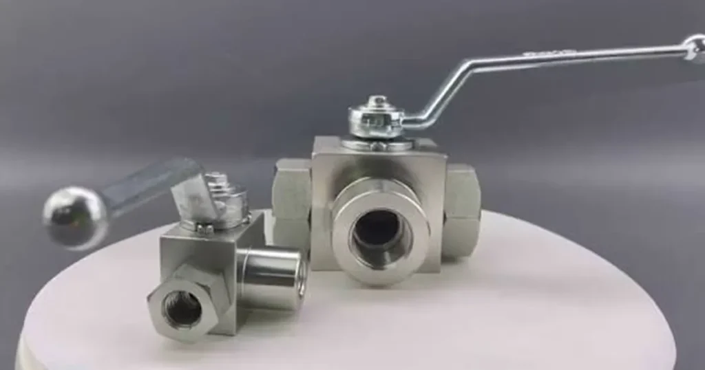
The movement is simple. The engineering around it is not. Hydraulic pressure loads the ball and seats, the stem has to transmit torque without creating an external leak path, and the bore has to pass the required flow without wasting too much pressure. If any of those details is wrong for your circuit, a valve that looks correct from the outside can run hot, become hard to turn, or fail to isolate the line.
What moves when you turn the handle?
The handle is fixed to a stem, and the stem engages the ball. Rotate the handle 90 degrees and the stem rotates the ball by the same amount. A mechanical stop normally limits travel at the fully open and fully closed positions.
Inside the ball is a bore. With that bore aligned to the inlet and outlet, oil passes through. Rotate the ball until the bore faces the body wall and the spherical surface presses against the seats. The flow path is blocked.
The ball and bore carry the flow
The bore is the working passage, so do not judge capacity from the thread label alone. A G 1/2 or NPT 1/2 connection tells you how the valve joins the line. It does not tell you the actual bore diameter, the smallest internal restriction, or the pressure drop at your flow rate.
A full-bore design can create a relatively straight path when open. A reduced-bore design may be smaller and lighter, but it adds velocity and pressure loss at the same flow. Before you choose one, compare the manufacturer’s pressure-drop curve or verified flow data at the relevant oil viscosity. The hydraulic ball-valve sizing data used in one technical catalog illustrates why bore and expected line flow must be checked together.
The seats stop internal flow
A seat supports the ball on each side and forms the shutoff seal. Depending on the valve design, hydraulic pressure, seat preload, seat geometry, and material behavior all influence how well the closed valve isolates the two ports.
This is also where temperature and fluid compatibility enter the decision. A seat material that works with petroleum-based hydraulic oil at one temperature may not be suitable for a different fluid or a hotter duty cycle. Use the pressure-temperature rating for the exact seat, seal, body, and valve size rather than borrowing a limit from another series.
The stem seals keep oil inside the body
The stem transfers handle or actuator torque to the ball. Its seals have a different job from the ball seats: they prevent oil from escaping around the stem to atmosphere. A valve can therefore have two separate leakage problems. Internal leakage passes across the closed ball and seats; external leakage appears around the stem, body joint, or connection.
If oil appears beneath the handle, tightening or forcing the handle does not solve the root cause. Depressurize the circuit, confirm the exact valve design, then inspect the stem sealing arrangement and allowable service procedure.
Open, closed, and partly open are three very different conditions
| Valve position | Internal flow path | What your system sees | Normal use |
|---|---|---|---|
| Fully open | Bore aligned with the ports | Maximum available flow with the valve’s minimum open-position pressure loss | Running the circuit |
| Fully closed | Solid ball surface across the ports | Line isolation within the valve’s verified leakage limits | Shutoff and service isolation |
| Partly open | Only part of the bore is exposed | A restricted, high-velocity flow path and a concentrated pressure drop | Usually not the right choice for precise hydraulic metering |
That middle position causes a common mistake. A partially open ball valve does reduce flow, but the adjustment is coarse. Much of the flow change can occur over a small handle movement, and the jet passes close to the seat edge. The resulting pressure drop turns hydraulic power into heat and may accelerate seat wear.
Note: Do not treat an ordinary hydraulic ball valve as a precision speed-control valve. A manufacturer catalog for industrial ball valves also warns that throttling may cause premature seal failure or make the handle difficult to operate. Use a purpose-built hydraulic flow control valve when your task is to meter flow rather than isolate it.
How does the closed valve seal under pressure?
You will often hear that pressure simply pushes the ball into the downstream seat. That describes the basic behavior of many floating-ball designs, but it should not be applied to every ball valve.
In a floating-ball valve, the ball has limited lateral movement. Differential pressure can load it toward one seat, which affects sealing force and operating torque. In a trunnion-mounted design, the ball is supported by fixed pivots and the seats may move toward the ball. The pressure-loading path is different, so the torque, seat design, and suitable size range can differ too.
For your circuit, the useful question is not only whether the valve is floating-ball or trunnion-mounted. Ask which port may be pressurized, whether reverse pressure is allowed, how a closed cavity relieves trapped pressure, and what leakage criterion applies. A two-way valve may look symmetrical without being rated identically in every pressure condition. Check the port marking and product documentation before assuming bidirectional shutoff.
What hydraulic pressure changes inside the valve
System pressure does not make the ball rotate faster. It changes the forces acting on the ball, seats, stem, body, and handle. As differential pressure rises across a closed valve, the contact load at the sealing surfaces may rise as well. That can increase breakaway torque, the effort needed to start opening the valve.
If a normally easy handle suddenly becomes stiff, stop forcing it. First check whether pressure is trapped on one side, whether the line has been isolated in the wrong sequence, and whether the valve is rated to open under that differential pressure. Also look for contamination, corrosion, distorted piping, damaged stops, and seat swelling. A longer wrench can hide the symptom while damaging the stem or handle.
Pressure also matters when the valve opens quickly. Releasing flow into a blocked, empty, or differently pressurized branch can create a transient shock. Where machine motion or stored energy is involved, use a controlled operating sequence and verify the complete circuit, not just the static valve rating.
Why flow direction still matters
A simple two-way ball valve may be designed for flow in either direction, but the valve body, cavity-relief feature, seats, or actuator arrangement can introduce a preferred direction. Three-way valves make orientation even more important because the ball has an L-port, T-port, or another drilled pattern that connects specific ports at each handle position.
Start with the port diagram, not the handle shape. Trace which ports connect at every permitted position and confirm whether the design allows a momentary blocked path or momentary port overlap during switching. The detailed ball valve flow-direction explanation helps you check the difference between a two-way path and multiport switching.
Manual and actuated ball valves use the same core mechanism
A lever gives you direct manual rotation and clear visual position. It is simple when the valve is accessible and the operating frequency is low. A pneumatic actuator applies torque remotely and can support automated sequencing, interlocks, or fail-position requirements if the complete actuator package is designed for them.
The actuator does not change how the ball blocks flow. It changes how torque reaches the stem. When you size one, allow for breakaway torque at the worst credible differential pressure and temperature, not only the smooth running torque of a new valve on a workbench. Also confirm mounting alignment, travel stops, cycle frequency, air supply, and the action required after loss of control power.
Choose the valve from the circuit, not from the port label
Before you select a hydraulic ball valve, collect the conditions that actually load it:
- Normal working pressure and credible peak pressure at every port
- Required flow and allowable pressure drop at operating oil temperature
- Hydraulic fluid, additives, and minimum and maximum fluid temperature
- Two-way isolation or three-way/four-way switching function
- Connection standard, nominal size, actual bore, and installation space
- Expected flow direction and any reverse-pressure condition
- Manual or actuated operation, cycle frequency, and required position indication
- Required internal and external leakage limits and the test conditions behind them
Then compare the exact series. The main ball valve types differ in body layout, port arrangement, mounting, bore, actuation, and service access. For high-pressure service, use the pressure-temperature information and dimensions for the selected size on the high-pressure ball valve page or its model drawing. Do not extend one model’s rating across the whole range.
What common symptoms tell you
| What you notice | Possible explanation | First check |
|---|---|---|
| Handle is suddenly hard to turn | High differential pressure, trapped pressure, contamination, corrosion, distorted installation, or seat damage | Depressurize safely and compare the condition with the valve’s allowed operating procedure |
| Oil appears around the stem | External stem-seal leakage or stem damage | Identify the leak point; do not confuse it with internal seat leakage |
| Pressure rises downstream while closed | Seat leakage, wrong port orientation, leakage through another circuit path, or thermal pressure change | Isolate the downstream volume and test the valve under defined pressure and temperature conditions |
| Machine slows or oil gets hotter after installation | Undersized bore, excessive line velocity, partial opening, or another restriction | Measure pressure immediately upstream and downstream while recording flow and oil temperature |
| Three-way valve sends flow to the wrong branch | Wrong ball pattern, incorrect port connection, actuator indexing, or stop setting | Compare every handle position with the port diagram |
These checks keep you from replacing a valve for a fault elsewhere in the circuit. A downstream pressure rise, for example, can come through a directional valve, cylinder seal, accumulator branch, or thermal expansion, not only across the ball seats.
Frequently asked questions
Is a ball valve fully open when the handle is parallel to the line?
That is common for a two-way manual valve, but do not use the handle alone as proof. Confirm the stop position and port marking, especially on three-way valves or valves with an actuator and separate position indicator.
Can a ball valve control hydraulic cylinder speed?
It can restrict flow when partly open, but the adjustment is usually too coarse for stable, repeatable speed control and can concentrate wear near the seats. The fuller discussion on whether you can use a ball valve to control flow explains the tradeoff.
Does a closed ball valve guarantee zero leakage?
No. Leakage performance depends on the exact design, seats, pressure differential, fluid, temperature, wear, contamination, and test method. Specify an allowable leakage rate and test condition instead of relying on an unqualified zero leakage claim.
Can you open a ball valve under full pressure?
Only if the selected valve and operating procedure allow the actual differential pressure and resulting torque. A system-pressure rating does not automatically mean the valve is safe to open against full differential pressure. Check the product documentation and stored-energy risks in the circuit.
Why does a ball valve have low pressure drop when open?
When the bore is aligned and close to the line’s internal diameter, oil follows a comparatively direct path. The real pressure drop still depends on bore size, internal geometry, flow, density, viscosity, and test conditions, so confirm it from a curve or measurement rather than assuming it is zero.
If you need a valve checked against a real hydraulic circuit, provide the working and peak pressure, required flow, fluid and temperature range, port standard, flow direction, bore requirement, and whether you need manual or pneumatic operation. Those details determine how the ball valve will behave after it leaves the catalog page and goes into your machine.