
A Code 61 and a Code 62 connection can both have four bolts and the same nominal port size. Put them side by side, though, and the bolt pattern, flange-head diameter, thickness, hardware, and seal details are not the same. If you order by pipe size and appearance alone, the replacement may reach your workshop and still not fit the machine.
The short answer to SAE Code 61 vs 62 is that Code 61 is the standard-pressure four-bolt flange series defined by SAE J518/1 and ISO 6162-1, while Code 62 is the high-pressure series defined by SAE J518/2 and ISO 6162-2. Code 62 generally uses a larger and heavier interface for the same nominal size. The two series are not interchangeable.
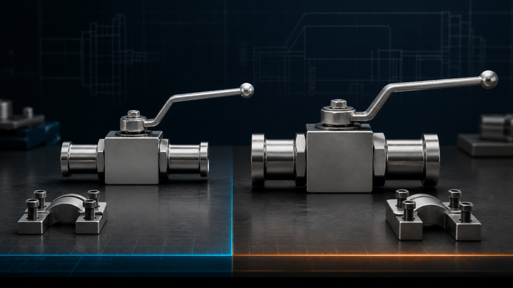
What Code 61 and Code 62 have in common
Both are hydraulic four-bolt flange connections. A typical assembly includes a flanged head, an O-ring in the flange-head groove, two split clamp halves or a one-piece clamp, four fasteners, and a flat port face.
The bolts supply clamping force. The O-ring creates the fluid seal between the flanged head and port face. Metal-to-metal contact around the interface helps contain the O-ring under pressure. This construction can be easier to assemble in large hydraulic lines than an equivalent large threaded connection because the required wrench swing and tightening effort are distributed among four fasteners.
The practical differences at a glance
| Feature | SAE Code 61 | SAE Code 62 |
|---|---|---|
| Pressure-series name | Standard-pressure series, often called SAE 3000 | High-pressure series, often called SAE 6000 |
| Main standard | SAE J518/1 and ISO 6162-1 | SAE J518/2 and ISO 6162-2 |
| Typical interface build | Smaller flange-head and bolt pattern for a given nominal size | Larger, thicker interface and heavier fastening arrangement |
| Size range | Extends to larger nominal sizes within the standard | Focused on high-pressure sizes within its stated range |
| Components | Code 61 flange head, clamps, bolts, port, and seal | Code 62 flange head, clamps, bolts, port, and seal |
| Interchangeable? | No. Use a matched connection of one code and size. | |
Do not reduce the comparison to “3,000 psi versus 6,000 psi.” Those names identify the series, while the permitted working pressure of Code 61 varies with size and every complete assembly is limited by its lowest-rated component.
Why the two codes are not interchangeable
For the same nominal size, Code 62 normally has a different flange-head diameter, head thickness, bolt-hole spacing, bolt size, clamp geometry, and O-ring requirement. The mismatch is intentional because the high-pressure series needs a different load path.
A part may appear to sit against the port while the head does not enter the clamp correctly. Bolt holes may be close but not aligned. Using smaller bolts in oversize holes or forcing a clamp over the wrong head does not create a qualified hybrid connection.
Note: Never enlarge holes, substitute clamps, or pull a mismatched SAE flange into position with the bolts. The joint may leak during commissioning or separate after pressure cycling.
If an adapter is required between two different interfaces, use a purpose-designed and rated adapter assembly. An adapter changes the connection; it does not make Code 61 and Code 62 components directly interchangeable.
How to identify Code 61 or Code 62 on existing equipment
Start with documentation. A drawing, part number, nameplate, hose tag, or service manual is more reliable than visual judgment. If the identification is missing, measure the interface systematically.
- Confirm nominal size. Record the flange or hose dash size. Do not confuse tube outside diameter, port bore, hose ID, and nominal flange size.
- Measure the bolt pattern. Check center-to-center spacing in both directions. Code 61 and Code 62 use different patterns for many corresponding sizes.
- Measure the flange-head diameter. Use the actual cylindrical head that enters the clamps, not the hose ferrule or nearby shoulder.
- Measure flange-head thickness. A similar diameter with a different thickness may indicate another interface or an equipment-specific variation.
- Identify the fasteners. Record bolt diameter, thread form, length, head type, and whether the port uses metric or inch threads.
- Check the O-ring groove and seal. Record groove diameter and seal cross-section where permitted by the service procedure.
- Compare with the controlled standard or manufacturer drawing. Match the complete set of dimensions, not one measurement.
Avoid three common identification traps
Nominal size does not identify the code
A 1-inch Code 61 flange and a 1-inch Code 62 flange both describe nominal size. That does not make their clamps or port patterns the same. Always state both size and code.
A four-bolt pattern is not automatically SAE J518
Other hydraulic and equipment-specific flange systems also use multiple bolts and O-ring sealing. Some were developed from common SAE patterns but differ in head thickness, bolt size, seal, or port dimensions. If one measurement does not match the standard table, stop and identify the equipment interface rather than forcing the nearest SAE part.
The O-ring is not selected by outside appearance
Seal size, hardness, and material must match the groove, fluid, temperature, and pressure duty. A seal that can be pushed into the groove may still have the wrong squeeze or volume. Reuse only when the applicable service instruction permits it and the seal condition passes inspection.
Which code should you choose for a new design?
The existing equipment port decides the code for a replacement. For a new design, pressure matters, but it is not the only variable.
Choose from Code 61 when its exact size-specific working pressure and the ratings of all connected parts cover normal pressure, transients, temperature, and duty. It offers a standard hydraulic interface and extends into larger size ranges.
Choose from Code 62 when the application needs the high-pressure series and compatible components are available for the selected size. Confirm that the pump, motor, valve, hose, tube, adapter, seal, and port all form a complete Code 62 pressure path.
Code 62 is not an automatic upgrade if the rest of the circuit remains lower-rated. It can also require more space because of its larger interface. Check clamp clearance, bolt access, hose bend radius, and service access in the actual machine layout.
Compare the full assembly, not only the flange
| Selection question | Why it matters |
|---|---|
| What are normal and peak pressures? | The selected assembly must suit steady operation and defined transients. |
| What flow and nominal size are required? | Port size affects velocity, pressure loss, hose size, and available code options. |
| Which equipment port is already present? | The port fixes the bolt pattern and sealing geometry for a replacement. |
| Is the hardware metric or inch? | Fastener threads and port details must match the controlled drawing. |
| What fluid and temperature are involved? | They influence O-ring and valve-seal compatibility. |
| Will the line vibrate or pull on the joint? | External load and poor support can damage an otherwise correct connection. |
| How will the valve be removed? | Clamp, bolt, actuator, and hose clearance affect maintainability. |
If you are choosing an isolation valve rather than only a connector, include the valve’s bore, working pressure, seat material, operation method, and face-to-face dimensions. The connection code tells you how the valve mounts; it does not tell you everything about how the valve performs.
Code 61 and Code 62 on Chenyang ball valves
Chenyang’s KHB-F3/6 and KHM-F3/6 ball valve series uses F3 for the SAE 3000-series connection and F6 for the SAE 6000-series connection. The published model table gives different flange dimensions for each series from DN13 to DN50.
When replacing one of these valves, match the complete model code and drawing. A KHB-25-F3 and KHB-25-F6 have the same DN25 nominal designation but different SAE interface dimensions. Do not order the F6 version simply because it sounds stronger if the machine has an F3 port.
For other flange styles, use the high-pressure flanged ball valve overview and the relevant product drawing. Round flanges, SAE flanges, and welded-flange designs should not be grouped together by appearance.
Installation checks after you identify the correct code
- Clean the flange head, port face, O-ring groove, clamps, and fasteners.
- Inspect sealing surfaces for scratches, corrosion, dents, and raised burrs.
- Install the specified new or approved reusable O-ring without twisting it.
- Bring the flanged head squarely against the port without using bolts to correct pipe misalignment.
- Use the specified clamp halves, washers, and fasteners for that code and size.
- Tighten fasteners gradually in a cross pattern to the controlled procedure.
- Support hoses and tubes so their weight and movement do not pry on the joint.
- Commission at controlled pressure, check for external leakage, and verify again after the initial operating cycle if the procedure requires it.
Never tighten a leaking high-pressure flange while it remains pressurized. Isolate, lock out, release stored energy, and confirm zero pressure before inspection.
What to send when you need a replacement
A useful replacement request includes:
- Existing manufacturer and full part number
- Code 61 or Code 62 marking, if present
- Nominal size and measured port bore
- Bolt spacing in both directions
- Flange-head diameter and thickness
- Bolt thread, diameter, and length
- Working and peak pressure
- Fluid and temperature range
- Valve face-to-face and installation-clearance dimensions
- Photos beside a ruler plus the equipment drawing
These details let Chenyang compare your interface with its published flanged ball valve dimensions instead of guessing from a product photo.
FAQ
What is the main difference between SAE Code 61 and Code 62?
Code 61 is the standard-pressure series and Code 62 is the high-pressure series. For the same nominal size, their flange-head dimensions, bolt patterns, clamps, hardware, and seals are generally different.
Can Code 61 and Code 62 use the same O-ring?
Do not assume they can. Seal dimensions are tied to the exact code and nominal size, and material must suit the fluid and temperature. Use the standard or product drawing.
Can I identify the code by bolt size alone?
No. Bolt size is one clue, but equipment-specific interfaces and metric or inch variants can cause confusion. Check bolt spacing, flange-head diameter, thickness, groove, and controlled documentation together.
Is Code 62 always better than Code 61?
No. It is the higher-pressure interface, but the correct choice is the one that matches the equipment port, verified pressure duty, size, space, and complete assembly. A mismatched Code 62 component is not safer than a correctly selected Code 61 assembly.
Are SAE J518 and ISO 6162 the same?
They are closely related standards for compatible four-bolt flange connections, with Code 61 corresponding to ISO 6162-1 and Code 62 corresponding to ISO 6162-2. Check the current editions and type details when a controlled drawing requires exact compliance.