
Your pump gauge may show plenty of pressure, yet a cylinder slows down when the required flow rises. Before you blame the pump, check how much of the pressure budget is being lost through the valve and the rest of the line.
A ball valve pressure drop calculation estimates the difference between pressure immediately upstream and downstream of the valve while fluid is flowing. For a fully open valve carrying a clean, single-phase liquid, the quickest method uses the manufacturer’s Cv or Kv value. It is useful for comparing valve sizes and port designs, but it is not a substitute for a complete hydraulic circuit calculation.
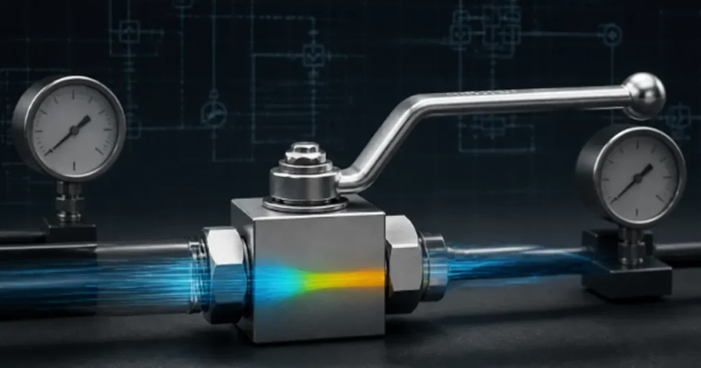
Pressure drop is not the same as pressure rating
Pressure rating tells you the pressure a particular valve can withstand under its specified conditions. Pressure drop tells you how much pressure is consumed in pushing a certain flow through that valve.
A valve rated for 315 bar can still have a pressure drop of only a fraction of a bar when it is fully open and correctly sized. Another valve with the same pressure rating may create a much larger loss because its bore is smaller or its internal path is more restrictive.
The basic measurement is:
Δp = p1 − p2
Here, p1 is the pressure measured just upstream of the valve, p2 is the downstream pressure, and Δp is the valve pressure drop. Measure both points under the same steady flow condition. A gauge at the pump and another several meters downstream will include pipe, fittings, filters, and elevation effects, so it will not isolate the valve.
Note: Never use the valve’s working-pressure rating as its Cv or Kv. Strength and flow capacity describe different properties.
The Cv formula for liquid flow
For basic liquid service in US units, the relationship is:
Δp = SG × (Q/Cv)²
Use:
- Δp in psi
- Q in US gallons per minute
- Cv from the valve manufacturer for the selected valve and opening
- SG as liquid specific gravity relative to water
Cv is the number of US gallons of water at 60°F that passes through a component in one minute with a pressure drop of 1 psi under the defined test convention. The formula can also be rearranged:
Q = Cv × √(Δp/SG)
Cv required = Q × √(SG/Δp allowed)
Cv is measured under standardized water-test conditions and links flow rate, pressure drop, and fluid specific gravity. When you select a valve, calculate the Cv your system needs, then check it against the verified Cv for the exact model and opening position. Do not borrow a generic figure from a similar-looking valve: bore size, seat geometry, port shape, and opening angle can all change the actual pressure drop.
A hydraulic oil calculation in US units
Assume your line requires 25 gpm of hydraulic oil. The oil has a specific gravity of 0.87 at the operating temperature, and the fully open ball valve has a published Cv of 40.
| Input | Value |
|---|---|
| Flow, Q | 25 gpm |
| Valve coefficient, Cv | 40 |
| Oil specific gravity, SG | 0.87 |
Insert the values:
Δp = 0.87 × (25/40)² = 0.34 psi
That is approximately 0.023 bar. Under these simplified conditions, the valve uses very little of the pressure budget.
Now compare a valve with Cv = 20 at the same flow:
Δp = 0.87 × (25/20)² = 1.36 psi
That is approximately 0.094 bar. Halving Cv increased the calculated loss by four times. The result still needs a viscosity check, but the comparison shows why connection size alone does not tell you flow performance.
The Kv formula in metric units
Kv expresses liquid capacity in cubic meters per hour with a 1 bar pressure drop for water under the defined convention. A commonly used simplified relationship is:
Δp = SG × (Q/Kv)²
Use Q in m³/h and Δp in bar. Do not mix gpm with Kv or m³/h with Cv.
Suppose a valve has Kv = 18 and carries 12 m³/h of oil with SG = 0.87:
Δp = 0.87 × (12/18)² = 0.39 bar
If flow doubles to 24 m³/h through the same valve:
Δp = 0.87 × (24/18)² = 1.55 bar
Doubling flow produced four times the pressure drop because Q is squared. In your machine, that extra loss can reduce pressure available to the actuator and turn more hydraulic power into heat.
Why a full-port valve usually loses less pressure
A full-port ball valve keeps the ball opening close to the connected line’s inside diameter. A reduced-port design narrows the flow, raises local velocity, and then expands the stream again downstream. The contraction, smaller passage, seat geometry, and expansion add resistance.
Do not classify a valve by the thread or flange size alone. Two DN25 valves can have different internal bore diameters and very different Cv values. Ask for:
- Actual ball-port diameter
- Full-port or reduced-port construction
- Published Cv or Kv for the exact model
- Fluid and test conditions behind the coefficient
- Pressure and temperature rating for your selected size and material
Chenyang’s hydraulic ball valve range includes different bodies, connection styles, and nominal sizes. That makes model-specific flow information more useful than a single value applied to the whole range.
When the simple Cv result is not enough
The basic equation is an estimate for liquid behavior close to the conditions represented by the coefficient. Several real hydraulic conditions can move the result away from that estimate.
High viscosity and cold starts
Hydraulic oil can be much more viscous during a cold start than at normal operating temperature. The basic Cv equation does not include a viscosity correction. If your system is slow only when cold, calculate with the oil’s viscosity at startup and use a suitable correction method or manufacturer flow curve.
Do not “fix” cold performance by opening a ball valve halfway. A standard ball valve is mainly an isolation device, not a stable precision throttle.
Partially open operation
The effective flow area changes sharply as the ball rotates. Cv at full open cannot be used for every intermediate position. A small change in angle may produce a large change in resistance, and the jet can load or erode soft seats.
If the task is to set actuator speed, use a purpose-designed hydraulic flow control valve. The article on using a ball valve to control flow explains the practical limits of leaving a ball valve partly open.
Cavitation and high pressure recovery
When local pressure inside a restriction falls toward the liquid’s vapor pressure, vapor bubbles can form and then collapse as pressure recovers. Noise, vibration, pitting, and unstable flow can follow. Ball valves can have high pressure recovery, so a modest measured downstream pressure does not guarantee that the minimum internal pressure stayed above the cavitation threshold.
The simple Cv equation predicts capacity; it does not by itself establish a safe cavitation limit. For a large pressure drop, hot oil, volatile liquid, or continuous throttling duty, use the valve manufacturer’s recovery data and an applicable valve-sizing method.
Flow regime and local installation effects
Elbows, reducers, pumps, and tees placed close to the valve can distort the velocity profile. Entrained air makes the fluid behavior different from a single-phase liquid. Contamination or a damaged seat can reduce the opening. Each condition changes what your pressure gauges see.
Using a K value when Cv is unavailable
A loss coefficient K can estimate local pressure loss from velocity:
Δp = K × ρ × v²/2
In this SI relationship, ρ is density in kg/m³, v is average velocity in m/s at the defined reference section, and Δp is in pascals. The difficulty is choosing the correct K. It depends on the actual valve geometry, port reduction, and opening angle.
Generic handbook K values can help with preliminary system estimates, but they are not product data. If the selection is sensitive to a few tenths of a bar, ask for tested Cv, Kv, or a pressure-drop curve.
Build a pressure budget before choosing the valve
A valve can look efficient in isolation while the complete branch still starves the actuator. Add the losses that occur at the required flow:
- Suction and return lines
- Pressure line and hose assemblies
- Elbows, tees, reducers, and quick couplings
- Filters, coolers, and manifolds
- Directional, check, throttle, and shut-off valves
- Elevation change where it matters
Then compare total loss with the pump operating point and the pressure the actuator needs under load. The hydraulic valve sizing process should combine flow capacity with working pressure, peak pressure, fluid, temperature, connection, and installation space.
How to verify pressure drop on the machine
- Warm the system to the specified operating temperature and confirm fluid condition.
- Measure actual flow through the branch. A pump displacement calculation alone may not equal delivered flow.
- Place suitable pressure measurement points close to the valve inlet and outlet.
- Record p1 and p2 at steady flow with the valve fully open.
- Repeat at the important operating flows and compare Δp with the predicted curve.
- If the measured loss is high, check whether the valve is reaching full travel, whether the installed model matches the drawing, and whether contamination or an adapter is restricting the path.
Use gauges or transducers with appropriate pressure range, accuracy, dynamic response, and safe connection practice. Isolate and depressurize the hydraulic system before changing test connections.
Information to send with a valve inquiry
For a useful pressure-drop review, provide the required and maximum flow, hydraulic fluid, density or specific gravity, viscosity at cold and normal temperatures, allowable valve pressure drop, working and peak pressure, port standard, line size, and whether the valve will remain fully open during operation.
If Cv data is unavailable for the shortlisted model, say so. An honest “data required” is safer than treating a generic value as a tested Chenyang result. For an application-specific review, include these conditions when contacting Chenyang about a high-pressure ball valve.
FAQ
Does a fully open ball valve have zero pressure drop?
No. A full-port valve can have a low loss, but its seats, bore, body transitions, and connections still create resistance. The actual loss rises with flow and depends on the model’s Cv or Kv.
Can I calculate ball valve pressure drop from pipe size alone?
Not reliably. Nominal size does not define the internal ball port or complete flow path. Use product-specific Cv, Kv, or a tested flow curve.
Why does pressure drop rise so quickly when flow increases?
In the basic liquid Cv relationship, pressure drop is proportional to flow squared. With the same valve and fluid, twice the flow produces roughly four times the pressure drop under the equation’s assumptions.
Should I use Cv or Kv?
Use the coefficient that matches your data and units. Cv is commonly paired with gpm and psi; Kv is commonly paired with m³/h and bar. Keep the full calculation in one unit system.
Does hydraulic oil viscosity affect the calculation?
Yes, especially at low flow, through small passages, or during cold starts. The simple Cv formula does not include viscosity correction, so use operating-temperature viscosity and a suitable correction method when the effect is significant.