
A valve body can meet its outside dimensions and still fail on the test bench. The spool drags in one position, a poppet guide wears unevenly, or internal leakage changes from one part to the next. When that happens, the drawing dimension marked on the main bore is only the first place to look.
Hydraulic valve bore finishing is the final machining and conditioning of a critical internal bore after drilling or rough boring. Its job is to bring diameter, form, alignment, surface texture, cross-hole edges, and cleanliness into the condition required by the mating part. Honing is common, but finishing may also involve precision boring, reaming, lapping, brushing, or a controlled combination of processes.
What matters is not whether the bore looks polished. It is whether the finished geometry and surface let the valve move, meter, guide, or seal as the design intended.
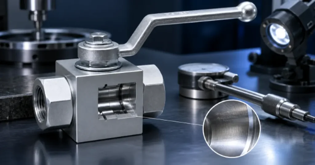
Why a finished bore changes valve performance
Picture a spool moving through several lands in a valve body. The diametral clearance has to be large enough for free movement after assembly and temperature change, yet controlled tightly enough to limit internal leakage. If one land is tapered, out of round, or offset from the others, the spool may touch locally even when every measured diameter appears to be within tolerance.
The same principle applies to a sleeve bore, poppet guide, stem bore, or cartridge cavity. The functional risk changes with the design, but the bore still locates a moving or sealing component. A form error can become friction. A torn or directional surface can damage a seal. A burr at a cross hole can break loose into the oil or catch the edge of a moving part.
| Bore condition | What you may see in the valve | Likely system effect |
|---|---|---|
| Diameter too large | Excessive clearance around the mating part | Higher internal leakage and weaker pressure holding |
| Diameter too small | Tight assembly or local contact | Sticking, slow response, or failure after warm-up |
| Taper or barrel shape | Clearance changes along the stroke | Position-dependent leakage or drag |
| Out-of-round bore | Uneven contact and leakage paths | Variable performance from part to part |
| Misaligned lands | A long spool binds even when local sizes pass | Hysteresis, erratic motion, or assembly rejection |
| Poor surface texture | High friction, seal damage, or poor oil-film behavior | Wear, leakage, and unstable actuation |
| Cross-hole burrs or loose abrasive | Scoring and contamination | Early failure elsewhere in the circuit |
This is why hydraulic valve machining has to connect drawing features with actual valve behavior. A pass/fail diameter alone cannot explain every leakage or sticking problem.
Diameter, geometry, and surface finish are different controls
These terms are often grouped together, but they answer different questions.
Diameter tells you the size at the points measured. Roundness describes how close one cross-section is to a true circle. Straightness concerns the bore axis or surface element. Cylindricity controls the complete three-dimensional form of the cylindrical surface. Coaxiality or position matters when several lands, seats, or connected features must share a functional axis.
Surface roughness, often reported as Ra, describes only part of the surface texture. Two bores can have the same Ra and still behave differently because their lay, peaks, valleys, torn material, waviness, or isolated scratches are different.
Note: A low Ra value does not prove that a valve bore is straight, round, correctly sized, or burr-free. If the part can stick or leak because of form error, the drawing and inspection plan need more than a roughness callout.
Start by asking what the bore does. A guide bore for a poppet does not automatically need the same texture or form controls as a close-clearance spool bore. The required acceptance limits must come from the valve design, material pair, operating temperature, fluid cleanliness, pressure differential, and leakage target. There is no responsible universal Ra or clearance value for every hydraulic valve.
Where bore finishing fits in the machining sequence
Finishing cannot rescue an unstable process indefinitely. The earlier operations must leave predictable stock, reliable datums, and enough geometric accuracy for the final tool to correct.
- Establish functional datums. Locate the bore from the same references that control the seat, mounting face, or connected port whenever the design requires that relationship.
- Drill or rough-bore the passage. Control drift, wall thickness, tool runout, and chip evacuation. A badly wandering hole may leave too little material on one side for final correction.
- Semi-finish the bore. Precision boring or reaming brings the feature close to final size and leaves a consistent finishing allowance.
- Finish the bore. Choose honing, fine boring, reaming, lapping, or another process according to geometry, material, production volume, and surface requirement.
- Deburr every intersecting passage. The edge must be safe for the moving part and the oil stream without rounding a metering edge that the design needs.
- Clean and inspect. Remove abrasive, chips, cutting fluid, and loosened burrs before a mating component enters the bore.
Heat treatment, plating, stress relief, and clamping can all change a bore. If one of those operations occurs after the last precision cut, the process plan must account for distortion or coating thickness. Measuring a perfect bore before the feature that changes it does not protect the finished assembly.
Choosing between boring, reaming, honing, and lapping
No process wins every job. The correct choice depends on how much material remains, which errors must be corrected, whether the bore is open or blind, and whether it contains separated lands or cross holes.
| Process | Best used for | Main limitation to watch |
|---|---|---|
| Precision boring | Controlling location and producing a predictable pre-finish bore | Tool deflection and machine geometry can leave taper or runout |
| Reaming | Efficient sizing where the pre-hole is straight and stock is uniform | A reamer tends to follow the existing hole and may not correct major position error |
| Multi-stroke honing | Correcting size, roundness, straightness, and surface condition with controlled abrasive action | Tool, stroke, overrun, stone expansion, and stock allowance must suit the bore |
| Single-pass bore finishing | High-volume production with stable pre-machining and progressive tools | It needs controlled incoming geometry and a validated tool sequence |
| Lapping | Very fine correction of selected precision surfaces | Process control, cleaning, and form retention require care |
| Flexible brushing | Edge conditioning and light surface improvement after cross drilling | It is not a substitute for correcting size or cylindricity |
Cross holes and metering edges need their own plan
A valve body often contains passages that break into a precision bore. The cutting edge can push material into the bore, and a finishing tool can fold or smear that material instead of removing it. If the edge is left sharp and ragged, it may score a spool. If it is rounded too aggressively, it may change a metering edge or flow area.
Before choosing a deburring method, identify whether the intersection is only a flow passage, a seal crossing, or a controlled metering feature. Then define the permitted edge condition on the drawing. “Deburr” without a measurable limit leaves too much room for interpretation.
After deburring, inspect from more than one direction when access allows. A borescope can reveal hanging material and scratches, but it does not replace dimensional or roughness measurement. Flush cleanliness also matters: a burr that is detached but still trapped inside the body remains a contamination risk.
How to inspect a finished hydraulic valve bore
Use the inspection method that can actually detect the drawing requirement. A go/no-go plug gauge is quick for size screening, but it cannot tell you where a bore is tapered, which land is misaligned, or why a spool binds.
| Characteristic | Useful inspection approach | What to avoid assuming |
|---|---|---|
| Local diameter | Air gauge, bore gauge, or calibrated internal measurement | One reading represents the full length |
| Roundness and cylindricity | Form measuring equipment or a validated multi-section method | Correct average diameter proves correct form |
| Land alignment | Functional master, air gauging strategy, or geometry measurement suited to the design | Each land passing separately guarantees free spool travel |
| Surface texture | Profilometer with the specified parameter, cutoff, and direction | Visual shine equals the required finish |
| Cross-hole edge | Magnified visual inspection, borescope, or validated edge check | Washing removes attached burrs |
| Cleanliness | Defined flushing, extraction, or particle inspection method | A dry-looking bore is clean |
Measure at enough axial and angular locations to find the error you care about. If taper is the concern, readings only at the center will miss it. If clamping distortion is suspected, compare the part in the inspection state that matches assembly conditions as closely as the control plan requires.
When the bore passes inspection but the valve still sticks
Do not immediately open the tolerance. First isolate where the resistance comes from.
- Confirm that the bore and mating part are clean and free from transport protection, chips, and abrasive residue.
- Check the spool, sleeve, stem, or poppet for size, straightness, burrs, coating buildup, and impact damage.
- Test movement dry only if the product procedure permits it; otherwise use the specified assembly fluid or lubricant.
- Look for housing distortion caused by mounting bolts, plugs, press fits, or uneven clamping.
- Compare cold and operating-temperature behavior. Different materials and local heating can change clearance.
- Review seal drag, spring side load, actuator alignment, and hydraulic side load before blaming the bore alone.
If leakage is the problem, separate the possible path. Internal leakage may pass through a bore clearance, across a seat, through a seal interface, or through an unintended manufacturing defect. The hydraulic valve testing process should tell you which function failed before machining changes are made.
What to put on the drawing and purchase specification
A useful bore requirement gives the supplier enough information to build and verify the function. It should identify the finished diameter and tolerance, relevant form controls, datum relationships, surface texture parameter, cross-hole edge requirement, coating or heat-treatment condition, cleanliness acceptance, and the mating component or functional test when applicable.
For a manufacturing review, prepare:
- Part material and heat-treatment condition
- Complete bore length, lands, interruptions, blind-end geometry, and cross holes
- Final diameter tolerance and required form or position controls
- Surface texture parameter and measurement conditions
- Stock allowance and the condition supplied to the finishing operation
- Plating, coating, or post-machining treatment
- Mating part dimensions and intended running clearance
- Leakage, movement, or pressure-test acceptance criteria
- Required inspection records and production quantity
That information is more useful than asking for “the smoothest possible bore.” A smoother surface is not automatically a better functional surface, and an isolated roughness target cannot replace control of geometry, alignment, and cleanliness.
FAQ
Is honing always required for a hydraulic valve bore?
No. Precision boring or reaming may be enough when the design tolerance, geometry, material, and production process allow it. Honing becomes valuable when the final operation must improve bore form and surface condition together.
What surface roughness should a hydraulic valve bore have?
There is no universal value. The correct specification depends on the mating part, clearance, sealing method, fluid, motion, and inspection method. Use the product drawing or a validated design requirement rather than copying a generic Ra number.
Can a plug gauge verify valve bore quality?
It can screen size and fit under defined conditions, but it does not fully measure taper, roundness, cylindricity, land alignment, or surface texture. Use it as one part of the inspection plan, not as proof of complete bore quality.
Why does a valve spool bind only after assembly?
Mounting loads, press fits, plug tightening, temperature change, contamination, seal drag, or actuator misalignment can distort or side-load the assembly. Compare the free component with the installed condition before changing the bore tolerance.
How does bore finishing affect internal leakage?
It influences the size and consistency of the clearance path between mating parts. Better geometry can make that path more predictable, but final leakage also depends on the mating component, pressure differential, fluid viscosity, temperature, and other sealing paths.
If you need a supplier to review a precision hydraulic valve feature, provide the drawing, material, critical tolerances, mating-part information, inspection requirement, and functional acceptance criteria. Chenyang can then determine whether the request fits its verified hydraulic valve product and manufacturing scope before quoting.