
You have a valve torque value of 60 N·m and an actuator rated for 80 N·m. That looks comfortable until you notice that the actuator rating is based on 6 bar air, while your machine sometimes falls to 4.5 bar. Or the 60 N·m value applies to a clean, frequently cycled valve at room temperature, not one that sits closed for months in dirty oil.
A reliable ball valve torque calculation starts with the exact valve manufacturer’s torque data at the worst differential pressure. You then apply the manufacturer’s service corrections and compare the result with actuator output at its weakest point and minimum available supply. Bore diameter and pressure alone can support an early estimate, but they do not give a defensible final actuator size.
That distinction matters in a hydraulic system. Too little torque leaves the valve partly open or closed. Too much available torque can twist the stem, overload the ball-to-stem drive, damage the seats, or hide a mechanical fault until something breaks.
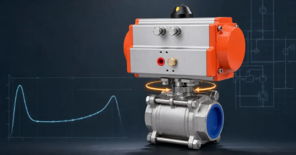
Know which torque value you are calculating
“Valve torque” is not one number throughout the 90-degree stroke. Ask for the torque profile, not just a value copied from a product table.
| Torque term | What it means | Why you need it |
|---|---|---|
| Break-to-open torque | Torque needed to start moving a fully closed ball away from its seat | Often governs opening after the valve has been stationary |
| Running torque | Torque while the ball travels between the end positions | Must remain below actuator output through the middle of the stroke |
| End-to-close torque | Torque needed near the final closed position | Determines whether the valve reaches its intended shutoff position |
| Break-to-close torque | Torque needed to start closing a valve that has remained fully open | Can matter when deposits, temperature or seat load change after long service |
| Maximum allowable stem torque | The highest torque the valve drive train may safely accept, when the manufacturer provides it | Prevents an oversized actuator from becoming a stem-damage source |
Breakaway is often the largest demand for a soft-seated floating ball valve, but “often” is not a design value. A special seat, heavy packing, a multipiece drive, a control port or an unusual pressure condition can move the peak elsewhere. Compare the whole valve demand profile with the whole actuator output profile.
Why there is no universal ball valve torque formula
The basic mechanics look simple: pressure loads the ball and seats, friction resists motion, and the stem applies a turning moment. The difficult part is knowing the real load and friction at the contact surfaces.
Seat preload exists even at zero differential pressure. Pressure can increase the contact load, especially in a floating-ball design where the ball moves toward the downstream seat. Stem packing, thrust washers, bearings, surface finish and assembly tolerances add resistance. Seat material, oil temperature, contamination, corrosion and time in one position can change it again.
Two valves can share the same DN, pressure rating and connection while needing different operating torque. A current ball valve actuator selection guide therefore starts with valve-specific torque tables, then applies documented application factors before selecting an actuator. That is the practical method: use the exact valve data and account for the real service condition.
If a web calculator asks only for valve size and pressure class, treat the result as a screening estimate. It cannot know the actual seat geometry, preload, packing adjustment or manufacturer-specific pressure loading.
Use this calculation workflow
1. Define the worst operating case
Start with pressure on both sides of the closed valve. Torque responds to differential pressure, not simply the pressure printed on the pump gauge.
delta p = p1 – p2
If the upstream side can reach 315 bar and the downstream side remains at 200 bar, the closed-valve differential is 115 bar, not 315 bar. If the downstream side can be drained while the upstream side stays pressurized, the worst case may be close to the full upstream pressure.
Also record minimum and maximum oil temperature, fluid type, contamination risk, cycling frequency, how long the valve may remain stationary, required opening or closing time, and the consequence of failing open or closed. For a pneumatic actuator, use the minimum pressure that can actually reach the actuator while other air consumers are running.
2. Get torque data for the exact valve configuration
Match the series, size, bore, pressure class or pressure rating, seat material, stem packing and operating direction. A torque chart for a PTFE-seated process valve is not transferable to a high-pressure hydraulic valve with a different seat and stem arrangement.
Check the chart conditions. Some tables apply at full rated differential pressure; others give torque against several pressure points. Some already include a factor, while others explicitly exclude safety or service factors. That note beneath the table is part of the calculation.
3. Apply only the factors the valve manufacturer specifies
A common calculation form is:
T_required = T_base x K_application
This form is valid only when the supplier defines a multiplicative application factor. Another guide may add several factor increments before multiplying, or publish corrected torque directly. Follow one method from one data set. Mixing factors from unrelated manufacturers can double-count margin or miss a condition entirely.
Typical reasons for correction include low temperature, long idle periods, infrequent emergency operation, dirty fluid, special seat material and modulating duty. Do not invent a factor because the condition “sounds severe.” Ask for one or agree on a project margin with the valve and actuator suppliers.
4. Compare torque at every critical actuator position
Actuator torque is also a profile. A double-acting pneumatic rack-and-pinion unit may change output slightly through the stroke. A spring-return actuator can have very different air-stroke and spring-stroke torque at the start and end. An electric actuator has startup, running and stall values, but stall torque is not a normal design target.
| Actuator arrangement | Minimum check | Common mistake |
|---|---|---|
| Double-acting pneumatic | Output at minimum air pressure exceeds valve demand through opening and closing | Using nominal plant air pressure instead of pressure at the actuator while it moves |
| Spring-return pneumatic | Both the weakest air-stroke point and weakest spring-stroke point exceed the corresponding valve demand | Checking only the high start torque and missing a weak end-of-stroke value |
| Electric quarter-turn | Startup and running output cover the valve profile without exceeding the permitted valve drive torque | Using motor stall torque as if it were continuous usable torque |
| Manual lever or gearbox | Required hand force and gearbox output stay within valve and operator limits | Adding a longer lever without checking stem strength |
For the KHB/KHM pneumatic-actuated valve range, Chenyang publishes a valve-and-actuator model pairing by size and pressure class. That pairing is the correct starting configuration; your actual air pressure, duty and service conditions still need confirmation.
The formulas are useful when you respect their limits
Turning moment
The basic torque relationship is:
T = F x r
T is torque, F is tangential force, and r is the perpendicular distance from the axis. This equation is exact for the applied force, but it does not tell you the resisting force inside the valve.
First-principles estimate
A simplified resistance model is:
T_est = mu x F_normal x r_effective + T_stem + T_bearing
The friction coefficient is mu. F_normal is the normal load at the ball-seat interface, including seat preload and pressure loading. T_stem and T_bearing represent packing, thrust washer and bearing resistance.
The equation explains why torque rises when contact load or friction rises. It is not enough for final sizing unless you have the valve’s seat geometry, preload, pressure-area model, friction data and assembly loads. Guessing those inputs can produce a precise-looking but wrong answer.
Manual handle force
Once you know the required valve torque, handle force is straightforward:
F_hand = T_required / L_handle
If required torque is 58 N·m and the effective handle length is 0.30 m, the tangential force is about 193 N, or about 43 lbf. A longer handle lowers the hand force, but it does not lower torque at the stem. It may simply make over-torque easier.
Worked example using manufacturer torque data
Consider a hypothetical hydraulic isolation valve. The numbers below illustrate the method; they are not Chenyang product data and should not be reused for a real valve.
| Input | Example value | Reason |
|---|---|---|
| Worst closed-valve differential pressure | 250 bar | Highest verified p1 minus p2 during operation |
| Manufacturer base torque at this condition | 48 N·m | Exact valve series, size and seat |
| Manufacturer-approved application factor | 1.20 | Illustrative correction for the defined duty |
| Minimum actuator output at weakest point | 75 N·m | Output at minimum available supply pressure |
T_required = 48 x 1.20 = 57.6 N·m
Round only after the calculation, so the required torque is about 58 N·m. The weakest actuator output is 75 N·m, which is above the corrected valve demand. The remaining ratio is 75 / 57.6 = 1.30.
Do not automatically add another 30% if the manufacturer’s 1.20 factor and the project specification already include margin. First identify what each factor covers. If the project requires an additional independent margin, apply it explicitly and recheck the actuator, coupling, bracket and maximum allowable stem torque.
Pressure and temperature can move the answer
A valve pressure rating answers whether the pressure boundary is suitable. It does not, by itself, give operating torque. You still need differential pressure across the ball and the torque conditions for that exact design. The distinction is worth checking when you review hydraulic ball valve pressure ratings.
Cold oil does not act directly on the seat like a new pressure load, but low temperature can change seal stiffness, packing friction, lubricant behavior and actuator air performance. Hot service can soften or expand polymer components and alter seal load. Use the valve and actuator temperature corrections rather than a generic percentage from another catalog.
Contamination is less predictable. Fine particles can increase friction or scratch the sealing surfaces; larger debris can obstruct rotation. If torque has increased in service, calculating a bigger actuator before finding the cause may turn a maintenance problem into a broken stem.
Do not confuse operating torque with assembly torque
Operating torque turns the ball through the stem. Stem nut torque, gland torque, body bolt torque and flange bolt torque are assembly values. They control preload in different joints and cannot be substituted for valve operating torque.
This confusion often starts with a datasheet column labeled only “torque.” Check the table heading and note. If the value is associated with bolts, nuts or packing adjustment, it is not the number used to size the actuator.
Common calculation mistakes
- Using maximum line pressure instead of the maximum possible differential pressure across the closed valve.
- Using nominal pipe size as the ball or bore diameter in a theoretical equation.
- Assuming every PTFE-seated valve has the same friction coefficient and seat preload.
- Checking only breakaway torque while ignoring closing and end-of-stroke demand.
- Reading pneumatic output at normal supply pressure rather than minimum pressure at the actuator inlet.
- Adding a generic safety factor without checking whether the valve torque data already includes service allowance.
- Choosing an oversized actuator without checking the stem, drive key, coupling and mounting bracket limits.
- Using a new, unpressurized bench measurement as the final value for an aged valve under full differential pressure.
If the valve already feels abnormal, work through the likely causes of a hard-to-turn hydraulic ball valve before increasing actuator size.
Can you measure ball valve torque in the field?
Yes, but the test condition must be defined. A calibrated torque transducer between the operator and stem can record breakaway, running and end torque. A torque wrench can support a controlled manual check on some valves, but it gives less information about the complete profile.
Record valve position, pressure on both ports, temperature, fluid, time since the last cycle and direction of travel. An unpressurized test is useful for identifying packing or mechanical friction, but it does not reproduce pressure-loaded seat torque.
Note: Never use a cheater bar on a pressurized valve to discover its torque limit. Isolate stored energy and follow the equipment lockout procedure before testing or disconnecting an operator. A longer lever can exceed the stem limit before the valve moves.
What to send with an actuator sizing request
- Valve manufacturer, exact series, size, bore and pressure rating
- Seat, seal and stem packing materials
- Maximum upstream and minimum downstream pressure during each operating direction
- Minimum and maximum fluid and ambient temperature
- Hydraulic fluid, contamination risk and any solids
- Cycle frequency, longest idle period and required operating time
- Manual, double-acting, spring-return or electric operation
- Minimum pneumatic supply pressure or electrical supply details
- Fail-open, fail-closed or stay-put requirement
- Any project margin and the allowable torque of the stem and mounting train
This information also helps you decide between a manual and pneumatic ball valve without treating convenience as the only selection factor.
Frequently asked questions
Can I calculate ball valve torque from pressure and diameter?
You can make a rough mechanics estimate if you know the effective pressure area, seat preload, friction, contact radius, packing torque and bearing torque. Pressure and nominal diameter alone are not enough for final actuator sizing. Use the exact valve torque curve or verified test data.
Is breakaway torque always the highest torque?
No. It is commonly critical for soft-seated ball valves, but seat design, packing, control geometry and service condition can put the maximum elsewhere. Check opening and closing across the full stroke.
What safety factor should I use?
There is no universal factor for every ball valve. Use the valve manufacturer’s application method and the project’s documented margin. Confirm whether published torque already includes an allowance so you do not count it twice.
How do I convert ball valve torque units?
Use 1 N·m = 8.8507 lbf·in and 1 lbf·ft = 1.3558 N·m. Keep extra digits during calculation and round the final selection value, not each intermediate step.
Does a longer handle reduce valve torque?
No. It reduces the force your hand must apply because the lever arm is longer. The stem still receives the same torque needed to move the ball, and an excessively long handle can help you exceed the valve’s allowable torque.
Can an actuator be too large?
Yes. More output may close a sticky valve, but it can also overload the stem, coupling, bracket or seats. Size above the required operating profile while staying within every mechanical limit and setting torque protection correctly.
If you need a torque review for a hydraulic ball valve, provide the valve model, pressure on both ports, seat material, temperature, duty and minimum actuator supply. Those details let the valve and actuator be checked as one operating package.