
A hydraulic rotary valve works by rotating an internal plug or spool to align or misalign internal flow passages, thereby controlling the direction, pressure, or on/off state of hydraulic oil in a high-pressure circuit. Unlike linear spool valves that shift axially, the rotary design uses angular motion — typically 90 degrees — to switch between flow paths.
Important: This guide covers rotary valves for hydraulic fluid control in high-pressure oil systems. If you are looking for a rotary airlock valve used in pneumatic powder conveying or bulk material handling, that is a different type of device and is not discussed here.
Key Takeaways
- A hydraulic rotary valve uses angular rotation of an internal plug or spool to control oil flow.
- The fundamental principle is aligning or blocking internal passages as the rotor turns.
- Key components include the rotor, stator body, flow ports, and high-pressure sealing elements.
- Rotary valves offer compact size and simpler actuation compared to axial spool valves.
- High-pressure applications above 315 Bar are common with properly sealed designs.
- They are widely used in directional control, emergency shut-off, and multi-circuit switching.
- The 2-way 2-position configuration is the most common for industrial hydraulic isolation tasks.
- Factors like port configuration, thread standard, and material choice directly affect system performance.
- Always verify pressure ratings, seal compatibility, and internal leakage specs before selecting a valve.
Key Components of a Hydraulic Rotary Valve
Every hydraulic rotary valve shares four essential components. Understanding each one makes the working principle easier to follow.
| Component | Function |
| Rotor (Internal Plug/Spool) | The rotating element with machined channels or flats. Its angular position determines which ports connect or block. |
| Stator / Valve Body | The stationary housing that encases the rotor and contains inlet and outlet ports. Typically machined from carbon steel or stainless steel. |
| Flow Passages & Ports | Drilled or machined channels in both the rotor and body. When aligned, they create a continuous flow path for hydraulic oil. |
| High-Pressure Seals & O-Rings | Prevent external leakage and minimize internal cross-port leakage. Materials include NBR, FKM (Viton), and PTFE, selected based on fluid compatibility and temperature. |
Tip: In high-pressure rotary valves (≥250 Bar), the clearance gap between rotor and body is typically held to 5-15 microns. Any larger, and internal leakage becomes unacceptable.
Step-by-Step: Working Principle of a Hydraulic Rotary Valve
The core mechanism is simple: a precision-machined rotor turns inside a closely fitted housing. Rotate the rotor, and the flow paths change. Most designs use a 90-degree angular stroke to switch between positions.
State 1: Open / Pass-Through Position
In the open position, the rotor’s internal channel aligns precisely with the inlet and outlet ports on the valve body. Hydraulic oil flows from Port P (pump side) to Port A (actuator side) with minimal pressure drop. The flow path is straight-through, making the pressure loss across the valve very low — typically under 1-2 Bar for a properly sized valve.
State 2: Closed / Blocked Position
When the rotor is turned 90 degrees (by a lever, electric actuator, or solenoid), the rotor channel rotates away from the port openings. The solid body of the rotor now faces the ports, creating a positive metal-to-metal seal that blocks oil flow. In this position, the valve isolates the downstream circuit completely.
Real-World Case Study: Chenyang ET2K Series
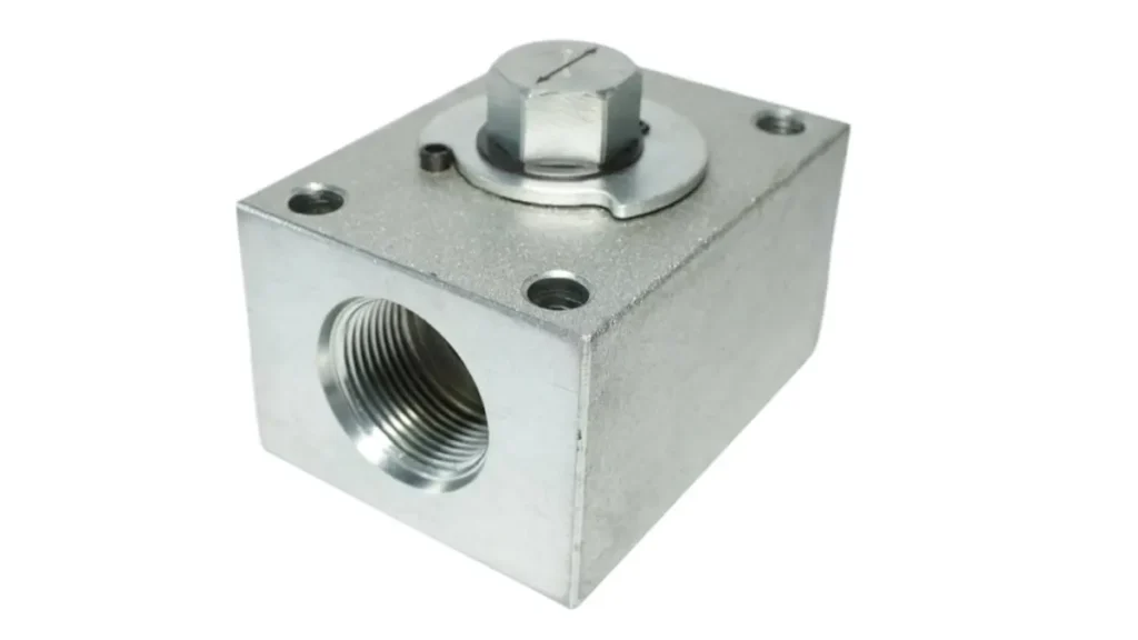
To see how this works in practice, consider the Chenyang Hydraulic ET2K Series 2-Way 2-Position Hydraulic Rotary Valve. This valve is designed for high-pressure hydraulic isolation and switching applications up to 315+ Bar.
The ET2K uses a hardened steel rotor with precision-ground channels inside a ductile iron body. When the operator rotates the handle 90 degrees, the rotor shifts from open to closed (or vice versa). NBR O-rings at each port interface prevent external leakage, while the tight rotor-to-body clearance keeps internal bypass flow below 0.15 ml/min at rated pressure.
This type of 2/2-way rotary valve is commonly found in hydraulic power units, machine tool clamping circuits, and emergency shut-off stations where a fast, reliable, mechanical isolation point is required.
Note: The ET2K is a manually actuated valve. For automated applications, rotary valves can also be driven by electric rotary actuators or pneumatic quarter-turn drives.
Common Port Configurations and Types
Hydraulic rotary valves come in several standard configurations. The port count and flow path design determine which applications a given valve suits.
| Configuration | Port Count | Function | Typical Use |
| 2-Way 2-Position (2/2) | 2 ports, 2 positions | On/off isolation | Pump isolation, accumulator dump, safety shut-off |
| 3-Way 2-Position (3/2) | 3 ports, 2 positions | Flow diversion between two circuits | Cylinder extend/retract, motor bypass |
| 4-Way 2-Position (4/2) | 4 ports, 2 positions | Directional control of double-acting actuators | Hydraulic cylinder reversal |
| 4-Way 3-Position (4/3) | 4 ports, 3 positions | Directional control with a center (neutral) position | Complex circuits requiring float or locked center |
Most standard industrial applications use the 2/2 or 3/2 configuration. The 4-way variants become necessary when you need to reverse the direction of a hydraulic cylinder or motor.
Tip: When selecting a port configuration, map out your complete hydraulic circuit first. A 2/2 valve can only isolate — if you need to divert flow to an alternate path, you need at minimum a 3/2 valve.
Hydraulic Rotary Valve vs. Hydraulic Spool Valve
Both rotary and spool valves serve directional control functions in hydraulic systems, but they operate very differently. The table below compares them head-to-head.
| Factor | Rotary Valve | Spool Valve |
| Mechanism | Rotor rotates around a fixed axis | Spool slides axially inside a bore |
| Actuation Force | Lower — angular motion requires less force | Higher — must overcome static friction along entire stroke |
| Compactness | Excellent — rotary design saves space | Moderate — requires axial clearance for spool travel |
| Internal Leakage at High Pressure | Low with tight clearance control (5-15 μm) | Varies — dependent on spool-bore fit and wear |
| Sealing Capability | Better for static sealing (O-ring at ports) | Relies on metal-to-metal clearance fit |
| Cost (typical) | Moderate for standard configurations | Lower for basic configurations, higher for proportional |
| Common Actuation | Manual lever, electric rotary actuator | Solenoid, pilot, hydraulic, manual lever |
| Maintenance | Simpler — fewer moving parts | More complex — spool wear, contamination sensitivity |
Bottom line: Choose a rotary valve when you need compact size, reliable high-pressure isolation, and simple manual or quarter-turn actuation. Choose a spool valve when you need proportional control, fast cycling, or solenoid-driven automation.
Typical Applications in Industrial Hydraulic Systems
Hydraulic rotary valves appear across a range of industries. Here are the most common deployment scenarios.
Construction Machinery
Excavators, cranes, and aerial work platforms use rotary valves in their outrigger control circuits and auxiliary hydraulic lines. The 6-way rotary valve configuration is particularly common in these machines, allowing a single valve body to manage multiple hydraulic functions. The compact form factor matters here — space inside a machine frame is always tight.
Machine Tools & Hydraulic Power Units
In CNC machining centers and hydraulic power units (HPUs), 2-way rotary valves serve as manual isolation points between the pump and the working circuit. When maintenance is required on a downstream component, the operator closes the rotary valve to isolate that section without depressurizing the entire system.
Emergency Shut-Off Systems
High-pressure hydraulic systems — especially those operating above 300 Bar — need reliable emergency isolation. A manually actuated 2/2 rotary valve provides a mechanical shut-off that does not depend on electrical power or pilot pressure. This makes it a preferred choice for safety-critical applications in steel mills, offshore equipment, and heavy presses.
Key Selection Factors for Engineers & Buyers
Choosing the right hydraulic rotary valve means evaluating several technical parameters. Getting any one of them wrong can lead to system failure.
| Selection Parameter | What to Check | Why It Matters |
| Working Pressure | Rated pressure in Bar or PSI — verify both static and dynamic ratings | A valve rated for 210 Bar will fail at 350 Bar |
| Flow Rate | Maximum flow capacity in L/min or GPM | Undersizing causes excessive pressure drop and heat |
| Port Thread Standard | BSPP (G), NPT, SAE, or Metric (M18×1.5, M22×1.5) | Mismatched threads leak or require adapters |
| Number of Ports/Positions | 2/2, 3/2, 4/2, 4/3 — match to your circuit design | Wrong configuration means the valve cannot perform the intended function |
| Body Material | Carbon steel (standard), stainless steel (corrosion resistance) | Stainless required for water-glycol fluids or marine environments |
| Seal Material | NBR (standard, -30°C to +100°C), FKM/Viton (high temp, +200°C), PTFE (chemical resistance) | Seal failure is the most common rotary valve failure mode |
| Actuation Type | Manual lever, electric rotary actuator, pneumatic quarter-turn | Determines whether the valve fits your automation strategy |
| Internal Leakage Rate | Typical spec: <0.15 ml/min at rated pressure | Excess internal leakage wastes energy and degrades system performance |
Tip: Always request a test certificate showing internal leakage measurements at rated pressure. A data sheet claim of “zero leakage” is not realistic for any rotary valve — there is always some bypass flow through the rotor-body clearance.
Conclusion & Sourcing Recommendation
A hydraulic rotary valve controls oil flow by rotating an internal plug to align or block flow passages — simple in principle, but demanding in execution. The precision machining of the rotor-body interface, the durability of sealing elements, and strict pressure testing determine whether the valve performs reliably at 300+ Bar or becomes a costly maintenance issue.
When evaluating hydraulic rotary valves, working directly with a source manufacturer ensures tighter quality control, flexible OEM customization, and direct factory technical support.
As an ISO 9001:2015 certified direct manufacturer of high-pressure hydraulic valves in China, Chenyang Hydraulic controls every production stage in-house — from precision CNC machining and thread processing to 100% factory pressure inspection. Whether you need standard ET2K Series 2-Way 2-Position Rotary Valves (available in G3/8, G1/2, M18x1.5, M22x1.5) or custom port configurations, our engineering team is here to support your fluid power applications.
Frequently Asked Questions
What is the main advantage of a 2-way rotary valve over a standard ball valve in hydraulic systems?
A 2-way hydraulic rotary valve offers lower internal leakage at sustained high pressure compared to a standard ball valve. The rotor-body interface in a rotary valve can be held to tighter clearances, and the sealing elements (O-rings at each port) provide positive static sealing. Ball valves rely on seat contact and can develop bypass paths as seats wear.
Can hydraulic rotary valves handle ultra-high pressure above 300 Bar?
Yes. Properly designed hydraulic rotary valves — such as the Chenyang ET2K series — are rated for continuous operation at 315+ Bar. The key factors are body material strength (ductile iron or forged steel), rotor hardness, and seal material selection. Always check the manufacturer’s rated pressure curve, not just the maximum static rating.
How do you prevent internal leakage in a hydraulic rotary valve?
Three things minimize internal leakage: (1) tight rotor-to-body clearance (typically 5-15 microns for high-pressure designs), (2) correct seal material for the fluid temperature and chemistry, and (3) proper filtration of the hydraulic oil — contamination particles accelerate rotor and seal wear. Regular inspection and replacement of O-rings at each port is standard preventive maintenance.