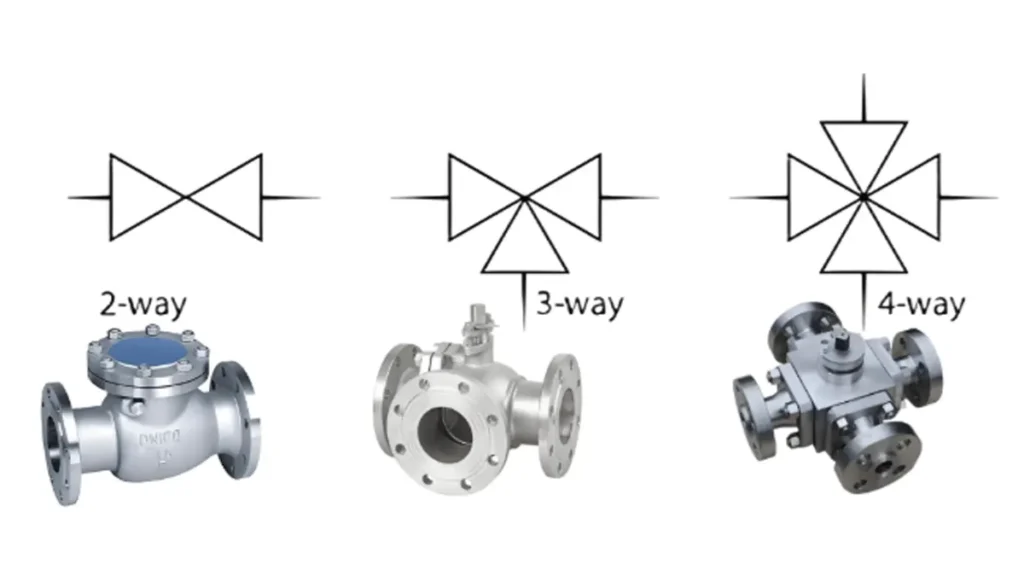
When you see a flanged ball valve symbol in a hydraulic or industrial diagram, you notice more than a simple shape. The ball valve symbol is often a circle. Flanged connections look like straight lines coming out from both ends. This symbol lets you find the valve type and connection quickly. You should remember to choose the right valve by looking at pressure, flange size, material, and working conditions.
Key Takeaways
- Flanged ball valve symbols look like circles with lines on both sides. These lines show flanged connections.
- Always check the legend in diagrams. It helps you know what each valve symbol means. Valve symbols can change by standard.
- Find arrows near the valve symbol. Arrows tell you if the valve is normally open or closed.
- The ball valve symbol shows the kind of valve. It does not show size, material, or pressure rating.
- Use the ball valve symbol to start. Always read notes and specs for full details.
- Flanged connections are best for high-pressure jobs. They spread stress evenly.
- When picking a valve, think about pressure class, material, and flow direction. This helps the valve work right.
- Knowing valve symbols makes hydraulic systems safer and better. It helps you pick the right valve.
What Is a Flanged Ball Valve Symbol?
Ball Valve Symbol Basics
Ball valve symbols are in lots of diagrams. These symbols help you find the valve type quickly. Most of the time, the ball valve symbol is a circle or a filled ball in the middle. This shape means there is a round part inside the valve. You can tell it is a ball valve because it has a mark in the center. Other valves, like globe or plug valves, use different shapes and do not have a ball. Ball valve symbols show turning, not straight movement. You should look at the legend in each diagram because the symbol can look different in each standard.
| Feature | Ball Valve Symbol | Other Valve Symbols |
|---|---|---|
| Closure Element | Central mark showing a round element | No special mark for closure element |
| Movement | Turns instead of moving straight | Usually moves in a straight line |
| Visual Representation | Circle or filled ball in the center | Changes by type (like globe, plug) |
| Interpretation Complexity | Check the legend for more details | Sometimes easier to understand |
| Design Variations | Different marks for different standards | Changes a lot between libraries |
You see ball valve symbols in piping and instrumentation diagrams a lot. These diagrams use symbols to show how flow is controlled. They help you learn how the system works.
Flanged Connection Representation
When you see a flanged ball valve symbol, you notice lines coming out from both sides of the circle. These lines mean the valve has flanged ends. Flanged connections make it simple to put in or take out the valve. You can spot this in a diagram by looking for lines that stick out at the ends of the ball valve symbol. Flanged ball valve symbols do not show things like flange size or bolt pattern. You need to read the notes or specs for that information.
Tip: Always check the legend and notes in the diagram. Standards like ANSI and ISO use different symbols for flanged ball valves. You might see these standards in chemical or water treatment plants.
| Standard | Industry Usage |
|---|---|
| ANSI | Chemical |
| ISO | Water Treatment |
How you use the ball valve symbol can change with working conditions. High heat or pressure can change the seat design and body material. The symbol does not show these things, so you must look at the specs.
| Aspect | Influence on Valve Selection |
|---|---|
| Construction | The ball valve symbol does not tell you what construction is needed for pressure, temperature, medium, or how often it is used. |
| Seat Design | The right seat depends on temperature and pressure difference. |
| Body Material | The material you pick depends on temperature and if it works with the chemicals. |
Industrial Applications
You find flanged ball valve symbols in many industries. Oil and gas, chemical plants, and factories use these symbols a lot. These places need good ways to control the flow of liquids and gases. Flanged ball valves can handle different pressures and temperatures. You see these symbols in diagrams because they help you see how the system is set up and pick the right valve for the job.
If you work with piping and instrumentation diagrams, you need to know how to read ball valve symbols. These symbols help you, but you still need to check the specs for things like material and pressure rating. Flanged ball valve symbols make your work easier by showing the connection type and what the valve does right away.
Flanged Ball Valve Symbol in P&IDs
Symbol Structure and Elements
When you look at a ball valve symbol in piping and instrumentation diagrams, you see more than just a circle. The main part is a round shape that stands for the ball inside the valve. A straight line runs through the circle, showing the path for flow control. Sometimes, you might spot extra notes or small letters next to the symbol. These give you more details about how the valve works or what conditions it can handle.
You will also notice that flanged connections have their own look. Small parallel lines at each end of the ball valve symbol show you that the valve uses flanges. These lines mean the valve connects to pipes with bolts, making it easy to remove or replace. Some diagrams even add tiny bolts or double lines to make this clearer. If you see these features, you know you are looking at a flanged ball valve symbol.
Tip: Always check for extra notes or tags near the valve symbols. These can tell you about pressure ratings, materials, or special features.
Open vs Closed State Indication
You might wonder how to tell if a valve is open or closed just by looking at the symbol. In many diagrams, arrows help you out. An arrow pointing toward the valve means it will close if something fails (fail-closed). If the arrow points away, the valve will stay open (fail-open). Sometimes, you see letters like NO (normally open) or NC (normally closed) right next to the ball valve symbol. These letters make it easy to know the default state of the valve.
| Symbol Direction | Meaning |
|---|---|
| Arrow Toward Valve | Fail-Closed |
| Arrow Away from Valve | Fail-Open |
| Symbol | Description |
|---|---|
| NO | Normally Open |
| NC | Normally Closed |
You should always look for these clues. They help you understand how the flow control mechanisms work in the system.
Flanged Ends in Diagrams
Flanged ends stand out in piping and instrumentation diagrams. You can spot them by looking for parallel lines at the ends of the ball valve symbol. Sometimes, you might see small squares or circles, filled or unfilled, to show different connection types. Flanged connections always use parallel lines, so you can tell them apart from threaded or welded joints.
Here’s a quick guide to help you:
| Connection Type | Visual Cues |
|---|---|
| Flanged | Parallel lines, filled/unfilled squares, circles |
| Threaded | Special symbols (not always shown) |
| Welded | Not always detailed |
| Socket Weld | Not always detailed |
- Flanged connections use parallel lines.
- Sometimes, you see extra shapes like squares or circles.
When you read a diagram, always check the ends of the valve symbols. This helps you pick the right valve for your job and avoid mistakes.
Flanged Ball Valve Symbol Diagram
Labeled Diagram Overview
You see a ball valve symbol in many diagrams. When you look at a flanged ball valve symbol, you notice several parts working together. Each part tells you something important about the valve and its role in the system. You might spot a circle in the center. That circle stands for the valve body. Marks around the body show how the valve connects to the pipeline. End marks tell you if the connection is flanged, threaded, or welded. Sometimes, you see tags or numbers next to the symbol. These tags link the valve to lists, datasheets, or maintenance records.
Here’s a simple breakdown of what you might see in a labeled diagram:
- The main circle shows the ball valve body.
- Parallel lines at each end mean flanged connections.
- Small marks or tags give extra information, like valve number or actuator type.
- Signal lines connect the valve to control instruments.
- Notes nearby explain special requirements, like fire-safe design.
Tip: Always check the legend in piping and instrumentation diagrams. Different companies use different symbols, so the legend helps you understand what each part means.
Meaning of Each Symbol Part
You can learn a lot from the parts of a ball valve symbol. Each piece has a job. Let’s break down what you see:
- Ball Valve Body Symbol: This part tells you the valve type. The circle means you’re looking at a ball valve.
- Marks Around the Body: These marks show how the valve connects to the line. They also point you to where specs are recorded.
- End Marks: These marks tell you the connection type. Parallel lines mean flanged joints. Other marks might show threaded or welded ends.
- Valve Tag: This tag links the symbol to the valve list, datasheet, and maintenance records. You can find more details about the valve here.
- Line Number: This number connects the valve location to nominal size, service, and piping class.
- Actuator or Instrument Tag: If you see extra symbols, you know the valve is operated by a motor or pneumatic system.
- Signal Line: This line shows the connection between the valve and the control instrument.
- Drawing Note: Sometimes, you see notes that define project-specific requirements, like locking or fire-safe design.
You can use this information to understand how the valve works and how it fits into the system. Each symbol part helps you make better choices for flow control mechanisms.
| Symbol Part | What It Means |
|---|---|
| Ball Valve Body | Valve type (ball valve) |
| Marks Around Body | Connection details and specs |
| End Marks | Connection type (flanged, threaded, welded) |
| Valve Tag | Links to datasheet and maintenance |
| Line Number | Pipe size and service info |
| Actuator/Instrument Tag | Operator or control-loop item |
| Signal Line | Connection to control instrument |
| Drawing Note | Special requirements (locking, fire-safe) |
How to Read the Diagram
You can read a ball valve symbol diagram step by step. This helps you avoid mistakes and pick the right valve for your job. Here’s a simple guide:
- Look at the valve body shape first. The circle tells you it’s a ball valve.
- Check for flow-direction markers. Arrows or symbols show how the flow moves.
- See if there’s an actuator symbol. Extra shapes mean the valve is operated remotely or automatically.
- Refer to the legend. Always check the diagram’s legend or notes for exact meaning.
- Understand the function. The symbol tells you if the valve is for shut-off, throttling, or safety.
Note: If you see parallel lines at the ends, you know the valve has flanged connections. If you spot tags or numbers, you can find more details in the valve list or datasheet.
You can use these steps to read valve symbols in piping and instrumentation diagrams. This makes it easier to understand how the system works and how each valve controls the flow.
Flanged vs Threaded Ball Valve Symbol
Key Differences in Symbols
You might wonder how to tell a flanged ball valve symbol from a threaded one. The answer is in the details. When you look at valve symbols in piping and instrumentation diagrams, you see that each connection type has its own look. Flanged ball valve symbols show parallel lines at each end of the main circle. These lines stand for the flanges that bolt the valve to the pipe. Threaded ball valve symbols look different. You often see short, zigzag lines or small notches at the ends. These marks show that the valve screws into place instead of using bolts.
Here’s a quick table to help you spot the differences:
| Feature | Flanged Ball Valve Symbol | Threaded Ball Valve Symbol |
|---|---|---|
| End Markings | Parallel lines (flange) | Zigzag or notched lines (thread) |
| Connection Method | Bolted flange | Screw thread |
| Common Use | High pressure, large pipes | Low pressure, small pipes |
| Symbol in Diagram | Circle with parallel lines | Circle with zigzag/notched ends |
You can use this table when you read a diagram. It helps you pick out the right ball valve symbol for your job. If you see parallel lines, you know it’s a flanged connection. If you see zigzags, you’re looking at a threaded one.
Why Flanged Matters in Hydraulics
You might ask, “Why does the flanged ball valve symbol matter so much in hydraulics?” The answer comes down to safety and performance. Flanged connections spread pressure across a ring of bolts. This design keeps the valve safe, even when the system runs at high pressure. Threaded connections focus stress on one point. That can turn into a weak spot if the pressure gets too high.
Let’s look at what makes flanged ball valves a smart choice for flow control mechanisms:
- Flanged connections prevent twisting stress. The bolts hold the valve steady, even if the pipes shake or vibrate.
- High-pressure lines need the strength of flanged valves. You don’t want a valve to blow apart during a pressure surge.
- Flanged ball valves use high-strength bolts. These bolts keep the valve secure, even in extreme conditions.
You see flanged ball valve symbols in diagrams for oil, gas, and chemical plants. These places need strong, safe valves. Threaded ball valves work best in low-pressure jobs or where you need a quick fix. When you read valve symbols, always check the ends. The right symbol helps you choose the safest option for your system.
If you want your hydraulic system to last, pay attention to the ball valve symbol. The symbol tells you more than just the valve type. It shows you how the valve connects and how safe it will be under pressure. That’s why you see flanged ball valve symbols in so many piping and instrumentation diagrams.
Symbol: What It Shows and Misses
Information Conveyed by the Symbol
When you look at a ball valve symbol in a diagram, you get a quick idea of what the valve does and how it connects. The symbol shows if it is a ball valve and how it joins to the pipe. You can spot flanged ends by looking for short lines on both sides of the symbol. If you see other marks, the connection could be threaded, butt-welded, or socket-welded. This helps you know how the valve fits in the system.
| Connection Type | Representation in P&ID |
|---|---|
| Flanged | Short parallel lines |
| Threaded | Different end marks |
| Butt-welded | Different end marks |
| Socket-welded | Different end marks |
You can use this table to figure out valve symbols in any diagram. It makes it easier to pick the right valve for your project.
Details Found in Notes and Specs
The ball valve symbol gives you some information, but not everything. You will not see pipe size, material, or pressure rating in the symbol. You need to check the notes and specs that come with the diagram. These extra details help you avoid mistakes and make sure the valve is right for the system.
Always look at the notes and specs before you buy or put in a valve. The symbol does not tell you all you need to know.
Here is a table that shows what you find in the notes and specs:
| Specification Type | Description |
|---|---|
| Line number / pipe code | Tells you which pipeline the valve is on, important for fixing and service. |
| Pipe size | Shows the size, must match the valve’s size. |
| Material or class | Tells you what the valve is made from, like stainless steel or carbon steel. |
| Pressure rating / service | Notes like ‘PN16’ show the system’s pressure and what rating the valve needs. |
| Valve function or service description | Says if the valve is for stopping flow, control, or safety. |
| Actuation / control information | Tells you if the valve uses a motor or needs special controls. |
You can find these details in the legend, notes, or bill of materials. They give you the missing information that the ball valve symbol does not show.
Importance of Full Specification
You might think the ball valve symbol tells you everything, but missing specs can cause big problems. If you skip the full specs, you could pick the wrong valve. This can break piping rules and even cause safety problems. You might get a valve that does not fit, cannot handle the pressure, or breaks when used. In steam service, mistakes like this can make the whole system unsafe and put people in danger.
Do not just use valve symbols. Always check the full specs before you choose a valve.
You should use the ball valve symbol as a guide, but always check the notes and specs for details. This keeps your system safe and makes sure everything works right.
Identifying Flanged Ball Valve Symbols
Step-by-Step Recognition
You might feel overwhelmed when you first look at a complex diagram. Don’t worry! You can spot a flanged ball valve symbol by following these steps:
- Find the Basic Shape
Start by searching for a circle with a line through its center. This shape stands for the ball inside the valve. - Look for Extra Markings
Check around the symbol for arrows or lines. These show you the flow direction or how the valve turns. - Read the Annotations
Sometimes, you’ll see numbers, letters, or words next to the ball valve symbol. These give you important details like pressure or material. - Notice Unique Features
Watch for special marks or shapes. Some companies use their own style for valve symbols, so you might see small changes. - Check the Legend
Always look at the legend or key on the diagram. It explains what each symbol means in that set of piping and instrumentation diagrams.
Tip: Take your time with each step. Rushing can lead to mistakes!
Common Mistakes to Avoid
Even experienced engineers make errors when reading valve symbols. Here are some common mistakes you should watch out for:
- Mixing up similar valve symbols, like globe valves and control valves.
- Reading the flow direction wrong because of confusing arrows.
- Missing the meaning of different line types, such as solid, dashed, or dotted lines.
- Skipping over tag numbers, which often hold key information about the valve.
Note: Always double-check both the symbol and any notes or tags nearby. These details help you avoid costly errors.
Real-World Schematic Examples
Imagine you’re working on a water treatment plant diagram. You see a circle with two parallel lines at each end. You check the legend and confirm it’s a flanged ball valve symbol. Next, you spot a tag number and look it up in the valve list. The list tells you the size, pressure rating, and material. By following these steps, you make sure you pick the right valve for the job.
You’ll find that most diagrams use the same basic shapes for valve symbols, but small differences can mean big changes in how the valve works. Always match what you see in the diagram with the notes and legend. This habit helps you avoid mistakes and keeps your system running safely.
Selecting a Flanged Ball Valve from a Symbol
Data Needed for Selection
When you see a ball valve symbol in a diagram, you need more than just the shape to pick the right valve. You have to gather some key data before you make a choice. This information helps you match the valve to your system and avoid problems later.
Here’s a table that shows what you should look for and where to find it:
| Specific Data Required | Importance for Valve Selection | Where to Confirm |
|---|---|---|
| Pressure class and design standard | Different classes change how the valve performs. | Piping class, valve list, project spec, or datasheet |
| Body, trim, and seat material | Materials react differently with fluids and temperatures. | Material spec, medium data, temperature, and corrosion notes |
| End connection and dimensions | The valve must fit your pipeline for easy installation. | Line spec, flange standard, installation drawing |
| Flow direction and position | How you install the valve can change how it works. | Flow arrow, datasheet, installation note, manufacturer drawing |
| Actuator signal and fail action | The right actuator keeps the valve working safely. | Instrument index, control plan, actuator datasheet, valve tag |
You can find most of this data in the notes, valve list, or specs that come with your piping and instrumentation diagrams.
Using the Symbol and Diagram for Sourcing
You can use the ball valve symbol as your starting point when you need to source a valve. The symbol tells you the type of valve and the connection style. If you see parallel lines at the ends, you know it’s a flanged connection. Tags or numbers next to the symbol link you to more details in the valve list or datasheet.
Here’s how you can use the diagram to help you order the right valve:
- Spot the ball valve symbol in the diagram.
- Check for tags, numbers, or notes next to the symbol.
- Look up these tags in the valve list or bill of materials.
- Match the connection type, size, and material to your pipeline.
- Confirm the pressure class and actuator type before you order.
Tip: Always double-check the specs and notes. The symbol gives you a quick idea, but the details make sure you get the right valve.
Example: High Pressure Applications
Let’s say you need a flanged ball valve for a high-pressure job. You can’t just pick any valve with the right symbol. You need to think about a few important things:
- Make sure the valve’s pressure rating matches your system’s highest pressure.
- Check that the valve can handle the hottest or coldest temperatures in your process.
- Pick materials that won’t rust or wear out from the fluid inside.
- Choose seals and seats that work with your fluid, especially if it’s rough or corrosive.
- If your valve sits outside, make sure it can handle rain, sun, or snow.
Flanged connections help spread out the force from high pressure. The bolts hold the valve tight and keep it safe, even if the pressure jumps. The strong body of a flanged ball valve also helps absorb shocks and keeps the seats working right. You get safe shut-off, even in emergencies.
When you use valve symbols in your diagrams, always remember that the symbol is just the first step. The details in the specs and notes help you pick a valve that will last and keep your system safe.
Conclusion
You can use valve symbols to find valve types and connections fast in diagrams. The flanged ball valve symbol is a special picture that helps you see how the system works. Look at this table to learn what the symbol tells you:
| Aspect | Explanation |
|---|---|
| Standardized Visual Language | The symbol is part of a standardized visual language. |
| Interpretation Importance | Understanding valve symbols is crucial for hydraulic systems. |
| Information Conveyed | The symbol shows valve type, connection, and operation. |
| Safety and Efficiency | This info keeps plant operations safe and efficient. |
You should always read the notes, BOM, and specs before picking a valve. Chenyang Hydraulic has KHBF and custom flanged ball valves for factories. Valve symbols help you, but you need to check the details before you buy or put in a valve.
FAQ
What does a flanged ball valve symbol look like?
You’ll see a circle with two parallel lines at each end. The circle means “ball valve.” The lines show “flanged” connections. This symbol helps you spot the valve type and how it connects in a diagram.
Why do diagrams use valve symbols?
Symbols make diagrams easy to read. You can quickly find valves and see how they fit in the system. This saves time and helps you avoid mistakes.
How can I tell if a valve is open or closed in a diagram?
Look for arrows or letters like “NO” (normally open) or “NC” (normally closed) near the symbol. These clues show the valve’s position.
Do all companies use the same valve symbols?
No, they don’t. Different standards like ANSI or ISO use different symbols. Always check the legend or key on your diagram.
What information does the symbol not show?
The symbol won’t tell you the valve’s size, material, or pressure rating. You need to check the notes, specs, or valve list for those details.
Can I use the symbol to order a valve?
Not by itself. The symbol helps you find the type and connection. You still need specs like size, material, and pressure rating before you order.
Where do I find more details about a valve in a diagram?
Check the tag number or notes next to the symbol. These link you to the valve list or datasheet for more information.