You find “SAE 3000” on one drawing and “Code 61” on another, so it is tempting to enter 3,000 psi as the connection rating and move on. That shortcut can be wrong. On some sizes the permitted working pressure is higher, on larger sizes it can be lower, and the complete assembly may be limited by the hose end, tube, valve, port, bolts, O-ring, or temperature before the flange pattern reaches its own limit.
An SAE flange pressure rating must be checked for the exact series, nominal size, component design, material, fasteners, seal, temperature, and service condition. “3000 psi” and “6000 psi” are widely used series names, not a promise that every assembled connection can operate continuously at that number.
Which standards define SAE four-bolt flange connections?
SAE J518 covers four-screw hydraulic flange connections used on tube, pipe, hose, valves, pumps, motors, and other fluid-power components. The current standard is divided into two main pressure series:
| Common name | SAE standard | Related ISO standard | Standard scope |
|---|---|---|---|
| Code 61 / standard-pressure series | SAE J518/1 | ISO 6162-1 | 3.5 to 35 MPa, depending on size and standardized conditions |
| Code 62 / high-pressure series | SAE J518/2 | ISO 6162-2 | 42 MPa series within the standard’s stated scope |
The SAE J518/1 description identifies Code 61 as the 3.5 to 35 MPa series. The SAE J518/2 description identifies Code 62 as the 42 MPa series and states an important selection rule: the assembly rating cannot exceed the lowest working-pressure rating of its components.
That last point is the one you need on the machine. A Code 62 port does not turn a lower-rated valve, hose, adapter, or tube into a 42 MPa component.
Why “SAE 3000” may not equal 3,000 psi
The traditional 3000 and 6000 labels are convenient shorthand. They do not replace the current size-specific table or the manufacturer’s product rating.
Code 61 covers a wider pressure range because the permitted value changes with nominal size and connection design. Smaller standard-series products may be rated above 3,000 psi, while large sizes can be substantially below it. Code 62 is intended for higher pressure, but the final assembly still has to be checked as a system.
Note: Treat “3000 psi series” and “6000 psi series” as interface families. Use the applicable standard table and the exact component data to establish maximum working pressure.
This distinction also matters when you read old drawings. A legacy description may use SAE J518C, ISO 6162, “SAE 3000,” “SAE 6000,” “Code 61,” or “Code 62.” Confirm which edition, type, fastener system, and nominal size the drawing expects rather than assuming the labels are interchangeable in every detail.
The weakest component sets the assembly rating
An SAE connection works as a matched assembly. The flange head carries the O-ring groove, the clamp and bolts generate clamping force, and the port face supports the seal. The connected valve, hose fitting, tube end, or adapter also has its own pressure boundary.
| Component or condition | How it can limit working pressure | What to verify |
|---|---|---|
| Flanged head or adapter | Material, wall section, manufacturing route, and size determine strength | Part number and manufacturer rating |
| Clamp halves or one-piece flange | Incorrect code, thickness, or material changes load capacity | Matching Code 61 or Code 62 kit |
| Bolts and washers | Wrong diameter, length, grade, or tightening method reduces clamp load | Specified hardware and torque procedure |
| O-ring | Wrong size, hardness, material, or damaged installation can leak below the structural limit | Seal specification, fluid, and temperature |
| Port or flange pad | Flatness, surface damage, thread depth, and surrounding wall affect the joint | Equipment drawing and inspection |
| Valve, hose, or tube | The attached product may have a lower maximum working pressure | Exact assembly data, not only the flange pattern |
| Temperature and environment | Seal properties, material strength, and corrosion condition can change allowable service | Manufacturer derating and compatibility data |
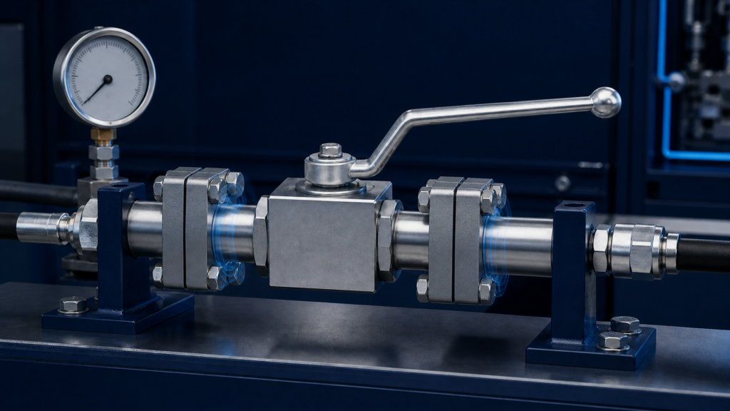
For a replacement valve, compare the pressure rating of the valve body and its SAE interface. A direct-mount ball valve can be lower-rated than the nominal flange series at a large size. The reverse can also happen: a strong valve body does not permit the attached hose assembly to exceed its own rating.
Working pressure, peak pressure, test pressure, and burst pressure
These numbers are not interchangeable.
Maximum working pressure is the allowable service pressure under specified conditions. It is the main value used for component selection.
Peak or transient pressure is the short pressure rise caused by rapid valve movement, load change, pump response, or hydraulic shock. Your design has to check whether the component rating and applicable design rules permit those transients.
Proof or test pressure is applied under a defined test procedure to verify integrity. A component surviving a test pressure does not mean that pressure is allowed for continuous service.
Burst pressure concerns structural failure during destructive testing. It is not an operating target and does not establish acceptable leakage or fatigue life.
When a catalog gives only a pressure-class name, ask for the actual maximum working pressure of the selected size. Do not reverse-engineer a continuous rating from a proof or burst value.
Static pressure is not the whole duty cycle
A flange on a steady test fixture and the same flange on a mobile hydraulic machine may see very different service. Repeated pressure cycles, vibration, pipe strain, bending load, thermal change, corrosion, and assembly disturbance all affect reliability.
If your line cycles between low and high pressure many times per hour, tell the supplier. If a heavy hose pulls sideways on the flange, support it. If the joint sits outdoors under salt spray, the hardware and surface protection need attention. A catalog pressure number cannot compensate for misalignment or an unsupported assembly.
The seal is static, but the joint still moves microscopically as pressure loads and unloads the components. Correct metal-to-metal support and bolt preload help keep the O-ring contained. Loose or uneven fasteners allow the interface to separate and can pump the seal out of its groove.
How temperature changes the decision
The flange metal, O-ring, connected valve, hose, and fluid each have temperature limits. NBR and FKM seals do not have identical low-temperature, high-temperature, or fluid-compatibility behavior. Even when the steel hardware remains strong enough, the seal may harden, swell, soften, or take excessive compression set.
Check temperature at the joint during the worst operating condition, not only ambient temperature. Oil returning from a loaded circuit can be much hotter than the surrounding air. For cold mobile equipment, confirm startup temperature and seal behavior before pressurizing the system fully.
Never copy a derating rule from a different material or manufacturer. Use the selected component’s data.
How to select an SAE flange pressure rating
- Record normal and peak pressure. Use measured or properly calculated transients where the application demands it.
- Identify the existing interface. Confirm Code 61 or Code 62, nominal size, metric or inch fastener version, port dimensions, and flange-head geometry.
- Check the exact standard table. Use the applicable SAE J518 or ISO 6162 edition for the size and connection type.
- List every pressure-containing component. Include the valve, flange head, clamp, port, hose or tube, adapter, and seal.
- Use the lowest verified rating. That value limits the assembly unless a qualified system design requires a still lower limit.
- Check fluid and temperature. Confirm O-ring, valve seat, body material, and surface protection.
- Review cyclic and external loads. Include vibration, pipe strain, hose weight, impact, and corrosion.
- Follow the specified assembly procedure. Clean faces, use correct hardware, lubricate only as instructed, tighten in stages, and verify the joint after commissioning.
If the pressure requirement is near the component limit, do not choose by series nickname. Obtain current drawings and ratings from the supplier.
How Chenyang identifies SAE flanged ball valve interfaces
Chenyang’s KHB-F3/6 and KHM-F3/6 SAE flanged high-pressure ball valves distinguish F3 3000-series and F6 6000-series flange connections. Published sizes cover DN13 to DN50 in the listed models, with separate interface dimensions for the two series.
That product coding identifies the connection family. The final selection still needs the exact model’s working pressure, system peak pressure, hydraulic fluid, temperature, and mating flange details. The broader high-pressure flanged ball valve range also states that pressure ratings vary by size.
If you are replacing an existing SAE valve, do not send only a photo. Provide the model marking, flange code, nominal size, bolt spacing, flange-head diameter and thickness, port dimensions, valve face-to-face length, and pressure requirement.
Installation mistakes that reduce the real pressure capability
Mixing Code 61 and Code 62 parts. The assemblies have different dimensions. A clamp that appears close enough may not seat correctly or provide the intended containment.
Using whatever bolts are available. Bolt diameter, grade, length, thread engagement, and tightening condition all matter. Substitute hardware only through an approved engineering decision.
Pulling misaligned pipework together with the bolts. The flange joint should not act as a pipe alignment tool. Side load can distort the joint and produce uneven seal compression.
Reusing a damaged O-ring. Cuts, flattening, hardening, contamination, and incompatible material can cause leakage even when the metal parts are correct.
Applying one torque value to every size. Torque depends on the specified fastener and assembly method. Use the product or standard procedure rather than an internet chart with unknown assumptions.
What to put on a purchase order
- SAE J518 Code 61 or Code 62, including applicable standard edition if controlled
- Nominal flange size and dash size
- Metric or inch fastener configuration
- Maximum working pressure and expected peak pressure
- Hydraulic fluid and operating temperature range
- Valve or fitting material and corrosion environment
- O-ring material requirement
- Complete mating dimensions or equipment drawing
- Required inspection, test, and documentation
A pressure-class label is not enough for a safe quote. When contacting Chenyang about an SAE flanged valve, include the machine drawing or a measured interface along with the operating data.
FAQ
Is SAE Code 61 always rated for 3,000 psi?
No. “3000 psi” is the common series name. The permitted working pressure varies by size and component design within the standard’s scope. Check the current standard and the exact product rating.
Is Code 62 always rated for 6,000 psi?
Code 62 is the high-pressure 42 MPa series, commonly called 6000 psi. The complete assembly still cannot exceed the lowest rating of its valve, flange components, hose or tube, port, seal, and other connected parts.
Can I use a Code 62 flange on a Code 61 port?
No. The flange-head dimensions, bolt pattern, clamps, hardware, and seals are series-specific. Do not mix them because the nominal pipe size is the same.
Does a higher flange rating increase the valve rating?
No. The valve body and internal design retain their own working-pressure limit. The assembly is governed by its lowest-rated pressure-containing component.
Where should I find the correct pressure rating?
Use the applicable SAE J518 or ISO 6162 standard, the exact valve or fitting catalog, the mating equipment drawing, and the hose or tube assembly data. Resolve any conflict with the responsible manufacturer or system engineer before installation.