
A hydraulic flow control valve diagram tells you more than where a valve sits. It shows which direction is metered, whether reverse flow can bypass the restriction, how the valve reacts to load-pressure changes, and whether the circuit is using meter-in, meter-out, or bleed-off control.
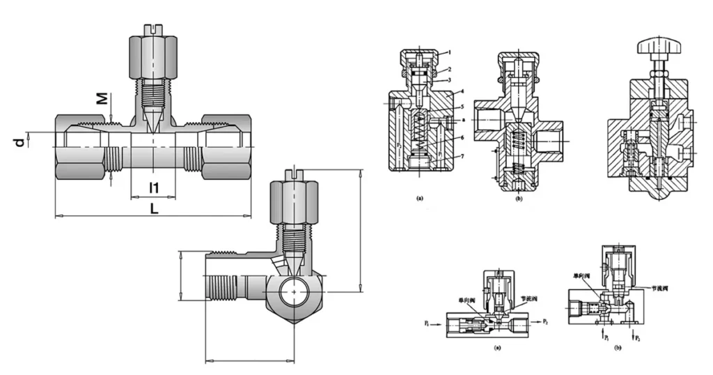
Read the complete flow path before turning an adjustment. The same valve can produce stable speed in one circuit and runaway motion, pressure intensification, or unnecessary heat in another.
The basic symbol behind a flow control valve
The simplest flow-control element is a restriction. A diagonal arrow through the restriction means the opening is adjustable. Without the arrow, the opening is fixed. If a check valve is drawn in parallel, oil can bypass the restriction in one direction while being metered in the other.
A separate compensating element indicates pressure compensation. That element changes the effective opening so the pressure differential across the metering orifice stays closer to a controlled value. An adjustable restriction alone is not pressure compensated.
These functional symbols are built using the rules in ISO 1219-1. A catalog drawing may show a simplified symbol or a detailed symbol with the compensator and sensing paths exposed.
| Diagram feature | Meaning | What you should check |
|---|---|---|
| Restriction without arrow | Fixed orifice | Hole size, expected pressure differential, contamination risk |
| Restriction with diagonal arrow | Adjustable throttle | Adjustment range, locking method, flow curve |
| Parallel check valve | Metered flow one way and freer flow the other way | Check orientation and cracking pressure |
| Compensator and sensing lines | Flow regulation against load-pressure variation | Required pressure margin and regulated-flow range |
| External drain or pilot line | Separate control-pressure path | Maximum drain pressure and correct routing |
Why a restriction changes flow
For an orifice, a useful simplified relationship is:
Q = Cd × A × √(2 × ΔP / ρ)
Flow Q depends on the discharge coefficient, opening area A, pressure differential (delta P), and fluid density (rho). If the opening stays fixed but load pressure changes, delta P changes and the flow changes. Oil viscosity and temperature also influence real valve performance, especially at small openings.
This is why a plain hydraulic throttle valve cannot guarantee constant actuator speed under every load. It sets a restriction. A pressure-compensated valve adds a mechanism that reduces the effect of changing pressure differential, provided the system has enough pressure available for regulation.
One-way and bidirectional flow control diagrams
One-way throttle with reverse free flow
In the metered direction, pressure pushes the check element onto its seat, so flow must pass through the adjustable restriction. In reverse, pressure unseats the check and most of the oil bypasses the restriction.
This is the functional principle of a unidirectional design such as the STU unidirectional throttle valve. Confirm the arrow or port marking on the actual product before installation; rotating the valve in the line can reverse which stroke is controlled.
Bidirectional throttle
A bidirectional throttle meters both directions through the same adjustable path. It works where both flow directions need restriction and a reverse bypass is not required. The STB bidirectional throttle valve is an example from Chenyang’s current product range.
Meter-in circuit diagram
Meter-in control restricts oil entering the actuator. For an ideal cylinder, velocity is approximately:
v = Q / A
Reducing inlet flow Q reduces the piston speed for the effective area A. This arrangement works best when the load resists motion. If gravity or another external force drives the actuator faster than the incoming oil can fill it, the inlet chamber can lose pressure and the load may run away or the circuit may cavitate.
Before using meter-in control, ask whether the load always opposes movement. A vertical descending load, flywheel, or motor driven by external torque often needs a different approach.
Meter-out circuit diagram
Meter-out control restricts oil leaving the actuator. The restriction creates back pressure, which can help control an overrunning load. It is common in cylinder lowering and other applications where the load tries to move faster than pump flow alone would command.
The benefit comes with a pressure risk. During cylinder extension, cap-end pressure acts over the full piston area while rod-end oil is forced through the meter-out restriction over the smaller annular area. Under simplified static conditions, rod-end pressure can rise above the supply-side value because of the area ratio. Friction, load, valve pressure drop, and circuit details change the exact result, but the design must check this pressure intensification.
Do not assume the pump relief setting limits pressure at every cylinder port. Verify the maximum possible pressure on the actuator, valve, hose, fittings, and return path.
Bleed-off circuit diagram
A bleed-off circuit diverts part of the pump flow to tank, leaving the remainder for the actuator. With a fixed-displacement pump, this can reduce the amount of flow forced across the main relief valve compared with some meter-in arrangements.
The actuator flow depends on the relative resistance of the working branch and bleed branch. Load changes can therefore change speed unless the circuit includes appropriate compensation. Bleed-off control also does not by itself restrain an overrunning load.
Pressure-compensated flow control diagram
A two-way compensated valve places a compensator in series with the metering orifice. The compensator senses pressures on both sides of the orifice and changes its opening to maintain a controlled differential. This makes flow less sensitive to load changes.
The valve still needs a minimum pressure differential to regulate. If inlet pressure falls or load pressure rises until the available margin is too small, the compensator reaches its limit and flow drops below the setting. The data sheet should state the regulated-flow range and conditions.
A three-way or priority flow control separates priority flow from excess flow. The diagram has an inlet, a controlled-flow outlet, and an excess-flow outlet. Do not confuse that with a two-way valve that simply creates a pressure drop in series.
When selecting a hydraulic flow control valve, review the pressure-drop/flow curve and operating conditions. ISO 4411:2019 specifies methods for determining steady-state differential-pressure/flow characteristics through hydraulic valve paths.
How to read a flow control diagram step by step
- Mark the pump, tank, actuator, and load direction.
- Find the restriction and determine whether it is fixed or adjustable.
- Look for a parallel check valve and trace both flow directions separately.
- Identify any compensator, pilot, or drain path.
- Decide whether the circuit is meter-in, meter-out, bleed-off, or priority flow.
- Calculate the flow needed for the target actuator speed.
- Estimate pressure at both valve ports in normal, stalled, and overrunning conditions.
- Check whether the valve can regulate across the expected viscosity, temperature, and load range.
- Confirm the failure behavior if the valve blocks, opens, loses adjustment, or the reverse check sticks.
Common diagram mistakes
| Mistake | What happens | Better check |
|---|---|---|
| Ignoring check-valve orientation | The wrong stroke is unrestricted | Trace each direction separately |
| Using meter-in on an overrunning load | Runaway motion or cavitation may occur | Analyze load direction and load-control needs |
| Assuming tank lines are pressure-free | Back pressure changes behavior and seal loading | Measure return pressure at operating flow |
| Ignoring pressure intensification | Rod-side components may see unexpectedly high pressure | Calculate cylinder area ratio and worst case |
| Equating port size with flow capacity | Excess pressure drop and heat | Use pressure-drop/flow data |
| Expecting constant speed from a plain throttle | Speed varies as load or viscosity changes | Use compensation when the application requires it |
| Using a shut-off ball valve for metering | Poor adjustment and possible seat damage | Use a throttle or flow-control design |
From diagram to product specification
The circuit tells you the function. The product specification must add working and peak pressure, controlled flow range, allowable pressure drop, adjustment resolution, flow direction, port size and standard, fluid, viscosity, temperature, seal material, mounting orientation, leakage requirement, contamination control, and lock or tamper protection.
If stable actuator speed is the goal, state the acceptable speed variation and load range. “Adjustable flow” is not enough. If the valve is only used to set commissioning speed, a simple throttle may be appropriate. If a load varies widely during every cycle, compensation may be necessary.
Chenyang also publishes a dedicated hydraulic speed control valve page for applications where the valve is selected around actuator speed rather than a generic flow setting.
FAQ
What does the arrow across a flow-control symbol mean?
A diagonal arrow through the restriction means the opening is adjustable. It does not, by itself, mean the valve is pressure compensated.
What does a check valve parallel to a throttle mean?
It means the valve meters flow in one direction and allows freer reverse flow through the check path. The check orientation determines which direction is controlled.
When should you use meter-out flow control?
Meter-out is often used when the load can overrun the actuator because the restricted outlet creates back pressure. You still need to check pressure intensification and use an appropriate load-control strategy.
Why does cylinder speed change after the oil warms up?
Lower viscosity changes leakage and the flow characteristics of a restriction. A non-compensated throttle is also sensitive to pressure differential, so temperature and load changes can both affect speed.
Can a flow control valve hold a suspended load?
A flow control valve meters movement but should not be treated as the sole safety device for a suspended load. The circuit may need a counterbalance valve, pilot-operated check valve, mechanical support, or another validated load-holding measure.
Send Chenyang your circuit and operating conditions
For a throttle or flow-control selection, send the diagram, desired actuator speed, cylinder dimensions or motor displacement, working and peak pressure, flow range, port standard, fluid, temperature, load direction, and required quantity. Contact Chenyang Hydraulic to compare the requirement with the current unidirectional, bidirectional, and flow-control product range.