
Hydraulic valve machining is not just about making a metal part match a drawing. The machined features form pressure boundaries, flow passages, sliding guides, threaded connections, and sealing interfaces. A small error in bore geometry, seat alignment, cross-hole deburring, or cleanliness can show up later as internal leakage, external leakage, sticking, high operating torque, or excessive pressure drop.
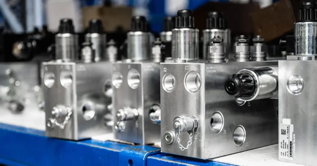
A dependable process connects each manufacturing step to a functional requirement. You should be able to trace a sealing test back to the seat geometry, a pressure-drop result back to the flow path, and a sticking problem back to bore condition, contamination, distortion, or assembly.
What parts of a hydraulic valve are machined?
The answer depends on whether the valve uses a ball, poppet, spool, or needle. A typical assembly may include a body, closure or metering element, stem or operator, seats, glands, plugs, springs, and connection parts. Soft seals are usually molded or cut rather than machined like metal, but their grooves and supporting surfaces are machined into the surrounding components.
| Component or feature | Machining objective | What can go wrong |
|---|---|---|
| Valve body | Hold pressure and locate all internal parts | Porosity, distortion, weak threads, misaligned bores, thin wall sections |
| Main bore or cavity | Guide a spool, poppet, ball seat, or cartridge | Taper, ovality, poor finish, incorrect diameter, embedded chips |
| Seat pocket or sealing face | Support a repeatable sealing line or area | Runout, waviness, scratches, burrs, wrong contact geometry |
| Flow passages and cross holes | Carry oil with the intended pressure loss | Breakthrough burrs, chips, sharp transitions, blocked drillings |
| Ports and threads | Connect the valve without leakage or damage | Wrong standard, poor pitch diameter, damaged sealing face, shallow engagement |
| Stem and operator interface | Transmit motion while maintaining alignment and sealing | Excessive runout, rough seal track, weak drive feature |
| Ball, poppet, or needle | Close or meter the flow path | Form error, poor surface finish, edge damage, mismatch with seat |
Start with a controlled material blank
Hydraulic valve bodies can begin as solid bar, forgings, castings, or near-net-shape blanks. The right choice depends on pressure, geometry, production volume, material, and cost. The blank must provide enough stock for finishing while maintaining the required material properties and pressure-boundary integrity.
Chenyang?s published hydraulic ball valve information describes carbon-steel and stainless-steel options and bodies produced from solid bar or forged blanks on applicable models. That does not mean every series uses the same material or blank. Confirm the exact grade, heat condition, and route on the model drawing or quotation.
Incoming inspection should verify material identity and condition before expensive machining begins. If traceability is required, define heat or batch records, identification method, and how marking will remain linked to the part after cutting and processing.
A practical hydraulic valve machining sequence
| Stage | Typical work | Control point |
|---|---|---|
| 1. Process planning | Define datums, setups, tooling, inspection points, and stock allowance | Critical features are machined from stable references |
| 2. Rough machining | Turn or mill the blank, establish reference surfaces, remove bulk stock | Leave balanced material for finishing and manage residual stress |
| 3. Passage and port machining | Drill, bore, ream, mill, and tap internal flow paths and connections | Depth, location, intersection, thread form, and minimum wall thickness |
| 4. Precision finishing | Finish bores, cavities, seats, faces, balls, stems, or needles | Size, form, position, surface condition, and fit |
| 5. Deburring | Remove edge and cross-hole burrs without changing metering geometry | No loose metal or sharp edge remains in the oil path |
| 6. Cleaning | Remove chips, abrasive residue, cutting oil, and cleaning chemistry | Internal passages are demonstrably clean and dry |
| 7. Surface treatment | Apply specified plating, conversion coating, passivation, or protection | Masking, thickness, adhesion, corrosion protection, and dimensional effect |
| 8. Final inspection | Measure critical dimensions, threads, sealing surfaces, and appearance | Drawing acceptance and calibrated inspection records |
| 9. Assembly and testing | Install seats, seals, closure parts, springs, plugs, and operators | Correct parts, cleanliness, torque, function, pressure, and leakage |
Datum strategy is more important than machine count
A modern machining center can hold tight size variation and still produce a valve that leaks if the critical features are not related to the right datum. A seat can be the correct diameter but misaligned with the ball or poppet. A port can pass a thread gauge but intersect the internal passage off-center. A mounting face can be flat yet incorrectly located relative to the bore.
Good process planning identifies the functional relationships first. Features that must be concentric, perpendicular, or accurately positioned should be machined from common or repeatable references where practical. If a part must be unclamped and reset, the fixture and probing plan need to control the setup error that the drawing allows.
Bores, seats, and sealing surfaces need different finishes
?Smooth? is not a complete requirement. A sliding bore, soft-seat pocket, metal seat, O-ring groove, and static gasket face perform different jobs. Each needs the right combination of dimensional accuracy, geometry, and surface texture.
A sliding spool bore must control clearance along its length. Too little clearance can cause sticking after thermal expansion or contamination. Too much increases internal leakage and reduces control. Depending on the design, boring, reaming, honing, grinding, or another finishing method may be used to achieve the specified bore.
A ball or poppet seat must contact the closure element in the intended location and width. Lapping may be appropriate for some metal-to-metal seat designs, but it is not a universal repair for every hydraulic valve. Soft seats depend on controlled support geometry, compression, and clean, undamaged contact surfaces.
Do not copy a generic roughness value from another valve. Surface specifications must come from the design, material pair, seal type, motion, lubrication, and leakage target.
Cross-hole burrs are a hydraulic problem, not a cosmetic one
Valve bodies often contain intersecting drilled passages. A burr at an internal intersection can break free, block a small control orifice, cut an O-ring during assembly, hold a poppet off its seat, or jam a moving element. A part can look clean from the outside while a dangerous burr remains deep inside the body.
Deburring methods include manual tooling, abrasive brushes, high-pressure water, thermal deburring, electrochemical deburring, or abrasive-flow methods. The correct process depends on material, passage access, burr size, production volume, and whether an edge forms part of a calibrated restriction.
The control question is not ?Was the part deburred?? Ask how hidden intersections are reached, how the process avoids rounding a functional edge, and how the result is inspected.
Threads and ports need both dimensional and sealing control
NPT, BSP/G, SAE, and metric ports are not interchangeable simply because their nominal diameters look similar. They differ in thread form, pitch, taper, sealing method, and reference dimensions. Some seal on the thread; others use an O-ring, bonded seal, cone, or face.
Thread inspection should match the connection standard and sealing design. A go/no-go gauge is useful, but it may not detect every problem on a sealing face, spotface, chamfer, or O-ring lead-in. Protect finished ports from handling damage and contamination after inspection.
Surface treatment can change fit and sealing
Plating and conversion coatings improve corrosion resistance or surface behavior, but they add thickness and can affect threads, bores, seal grooves, and mating faces. The drawing and process plan should define which areas receive coating, which areas are masked, and whether final dimensions apply before or after treatment.
Chenyang publishes several treatment options across its current range, but availability depends on the product and application. Do not assume one coating or color applies to every high-pressure hydraulic ball valve.
Cleaning must remove what machining creates
Machining introduces chips, fines, cutting fluid, abrasive media, and handling residue. If these remain inside a valve, the new component can contaminate the system during its first operating cycle.
Cleaning should reach blind holes, cross passages, threads, and small restrictions. The method must be compatible with the base material, coating, seals, and hydraulic fluid. After cleaning, use controlled drying, protected storage, and capped ports to prevent recontamination.
ISO 4406:2021 defines the code used to state solid-particle contamination levels in hydraulic fluid. It does not set one universal cleanliness target for every valve. The required level comes from the system and its most contamination-sensitive components.
Inspection should predict function
| Inspection | What it verifies | Functional link |
|---|---|---|
| Material verification | Grade or alloy identity | Strength, corrosion behavior, heat treatment, and compatibility |
| Dimensional inspection | Sizes, depths, locations, and clearances | Assembly fit, wall thickness, motion, and flow path |
| Form and position inspection | Roundness, cylindricity, runout, flatness, perpendicularity, position | Alignment, sealing contact, spool motion, and port intersection |
| Surface inspection | Texture, scratches, burrs, coating condition | Seal life, leakage, friction, and contamination risk |
| Thread and port inspection | Thread form and sealing geometry | Connection strength and external leakage |
| Pressure and leakage testing | Pressure boundary and closure performance | Validates the assembled valve under defined conditions |
| Pressure-drop or flow test | Hydraulic resistance through a flow path | Heat, efficiency, and usable flow capacity |
A coordinate measuring machine, bore gauge, thread gauge, profilometer, optical system, or air gauge is only useful if the method suits the feature and the measurement uncertainty fits the tolerance. Ask for the inspection plan and acceptance criteria, not just a list of equipment.
Machining defects and the failures they cause
| Manufacturing issue | Possible field symptom | Likely mechanism |
|---|---|---|
| Seat misalignment | Internal leakage or high operating torque | Uneven contact between closure element and seat |
| Bore taper or ovality | Spool sticking or inconsistent leakage | Clearance changes along or around the bore |
| Cross-hole burr | Intermittent sticking, damaged seals, blocked orifice | Loose metal or sharp internal edge |
| Poor thread or sealing face | External leakage or damaged fitting | Incorrect engagement or seal compression |
| Coating on a critical fit | Difficult assembly or restricted movement | Uncontrolled added thickness |
| Residual abrasive or chips | Early wear, seat leakage, or system contamination | Inadequate cleaning after finishing |
| Incorrect assembly torque | Distortion, leakage, or loosened parts | Under-clamping or excessive preload |
What to include in an RFQ for a machined hydraulic valve
- Complete drawing with revision level, units, datums, tolerances, and surface requirements.
- Valve function and circuit, not just the component geometry.
- Working pressure, peak pressure, test requirement, and fluid.
- Required flow and allowable pressure drop.
- Material grade, heat treatment, coating, and corrosion environment.
- Port and thread standards, sealing method, and mating parts.
- Seat, seal, and leakage requirements with test conditions.
- Cleanliness, packaging, traceability, inspection report, and sample approval requirements.
- Annual quantity, batch size, target schedule, and change-control expectations.
Chenyang?s manufacturing overview lists CNC machining, valve-body processing, assembly, seal installation, and pressure testing. For a custom project, confirm the process and documentation needed for your exact model instead of assuming the same controls apply to every part.
FAQ
Why are hydraulic valve tolerances tight?
Clearances and alignment affect motion, leakage, pressure drop, and sealing. The required tolerance is feature specific; tighter is not automatically better if it increases cost without improving function.
Why is honing used in hydraulic valve machining?
Honing can improve bore size, geometry, and surface condition after earlier operations. It is useful for certain precision bores, but the design and process plan determine whether honing, grinding, reaming, or another method is appropriate.
Why is deburring so important in a valve body?
Internal burrs can detach, jam moving parts, block orifices, damage seals, or contaminate the system. Cross-hole intersections deserve special attention because they can be difficult to reach and inspect.
Does passing a dimensional inspection prove the valve will not leak?
No. Dimensions support performance, but the assembled valve also needs appropriate pressure, leakage, and functional testing under defined fluid, temperature, pressure, and time conditions.
What should you ask a hydraulic valve machining supplier?
Ask how critical features are datumed and inspected, how internal burrs and chips are removed, how coating thickness is controlled, what test conditions are used, and how results remain traceable to the production batch.
Discuss your valve drawing with Chenyang
Send your valve type, drawing, working and peak pressure, flow, port standard, material, seal requirements, surface treatment, quantity, and inspection expectations. Review the current Chenyang product range or contact Chenyang Hydraulic for a model or OEM assessment.